


V4062A,B,D HI-LO-OFF FLUID POWER GAS VALVE ACTUATOR
60-2099—8 4
INSTALLATION
When Installing This Product…
1. Read these instructions carefully. Failure to follow them
could damage the product or cause a hazardous
condition.
2. Check the ratings given in the instructions and on the
product to make sure the product is suitable for your
application.
3. Installer must be a trained experienced, flame
safeguard control technician.
4. After installation is complete, check out product
operation as prided in these instructions.
WARNING
Electrical Shock Hazard.
Can cause serious injury or death.
Disconnect power supply before making wiring
connections to prevent electrical shock and
equipment damage.
IMPORTANT
1. All wiring must comply with all applicable electrical
codes, ordinances, and regulations. All wiring must
be NEC Class 1.
2. Voltage and frequency of the power supply
connected to this control must agree with those
marked on the device.
3. Loads connected to the auxiliary switch and/or
proof-of-closure switch, if used, must not exceed
the ratings given in the Specifications section.
4. When replacing a V6034 Actuator with a V4062, the
V5034 Valve body must be changed to a V5055
Valve.
5. Do not attempt to use the V4062 Actuator with the
V4055/V5034 Adapter. Differences in stem travel
can prevent correct low fire adjustment.
Install Valve
The actuator is installed directly on the V5055/V5097 body
after the valve is installed in the gas supply line. Refer to the
instructions packed with the V5055/V5097 Gas Valve for
installation details. When installing the valve, assure that:
1. Sufficient clearance is allowed for actuator installation
and service.
2. Ambient temperatures at the valve location do not
exceed actuator ratings.
3. Position of the valve permits damper hookup if one is
controlled.
Install Accessory Switches (If Needed)
An spdt switch can be installed to operate an auxiliary load
up to 1/2 hp (0.37 kW). The switch can be adjusted to
operate at any point in the valve stroke.
A proof-of-closure switch can also be installed with a V5055/
V5097C or E Valve (with double seal) on any V4062 Actuator
to provide a valve seal overtravel interlock. The spdt proof-of-
closure switch is installed to make or break a circuit when
the valve is in the closed position. The switch is not
adjustable.
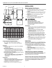
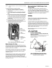
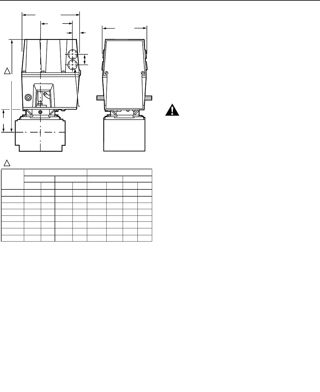
Fig. 1. Approximate mounting dimensions
of V4062 Actuators in in. (mm).
Ambient Operating Temperature Rating:
-40° to 150°F (-40° to 66°C) for 60 Hz models;
-10° to 158°F (-23° to 70°C) for 50 Hz and 50/60 Hz
models.
Approvals:
Underwriters Laboratories Inc. Listed: File No. MH1639,
Guide No. YIOZ.
Factory Mutual: Approved.
International Approval Services (Joint Venture of the
American Gas Association [AGA] and the Canadian
Gas Association [CGA]): Certified 60 Hz models only.
Industrial Risk Insurers Acceptable.
Some V4062 Actuators are approved as Class A valves in
accordance with EN161:
When used with V5055 Valves: Pin: CE-0063AR1359.
When used with VE5000 Series Valves: Pin: CE-
0063AP3075.
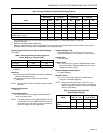
Accessories:
133568 Auxiliary Switch Bag Assembly.
133569 Proof-of-Closure Switch Bag Assembly. (Must be
used with a V5055/V5097C or E with double seal).
135796 Wrench (included with the actuator).
7616BR Damper Crank Arm (damper arm and clip).
B
A
1
1
(32.5)
KNOCKOUT
FOR 1/2 INCH
CONDUIT (4)
5 (127.0)
1-9/32
27/32
(21.4)
3-23/32
(94.5)
6-3/4 (171.5)
ALLOW 4 IN. (101.6 MM) CLEARANCE FOR ACTUATOR REMOVAL.
M10981
3/4
1
1-1/4
1-1/2
2
2-1/2
3
4
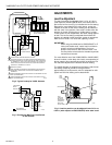
VALVE SIZE
INCH
11-1/8
11-1/8
11-1/8
11-1/8
11-1/4
11-3/4
11-3/4
14-1/8
282.6
282.6
282.6
282.6
285.8
298.5
298.5
358.8
2-3/4
2-3/4
2-3/4
2-3/4
2-7/8
3-3/8
3-3/8
5-13/16
69.9
69.9
69.9
69.9
73.0
85.7
85.7
147.6
11-1/8
11-1/8
11-1/8
11-1/8
11-3/4
11-3/4
11-3/4
—
283
283
283
283
298
298
298
—
2-3/4
2-3/4
2-3/4
2-3/4
3-3/8
3-3/8
3-3/8
—
70
70
70
70
86
86
86
—
DIM A
V5055 V5097
IN. MM
DIM B
IN. MM
DIM A
IN. MM
DIM B
IN. MM
VALVE
VALVE