


3 69-0510—4
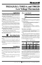
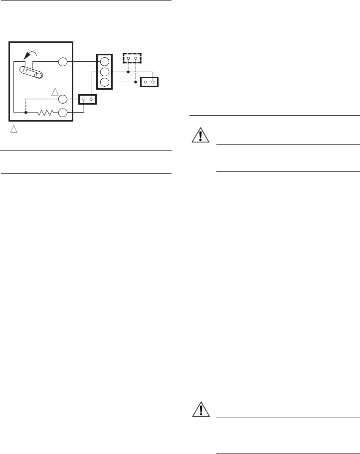
Fig. 6—TS822A in typical millivoltage heating
application.
Setting and Adjustment
TEMPERATURE SETTING
Move the temperature setting lever to the desired control
point on the temperature scale. On positive off models, the
control circuit is broken when the lever is moved to the
extreme low end of the temperature scale. On models with
temperature range stops, move the temperature setting le-
ver only between the two temperature range stops.
HEAT ANTICIPATOR SETTING (T822D,F,G
ONLY)
NOTE: Before Changing your heat anticipator setting,
consult your installing contractor or equipment manu-
facturer. Heat anticipators on some models are fac-
tory set to the manufacturer's specifications.
IMPORTANT: The T822D,F,G has an adjustable heat
anticipator and operates properly ONLY IF THE
ANTICIPATOR IS ADJUSTED TO MATCH THE
CURRENT DRAW OF THE PRIMARY CONTROL.
Use the T822D,F,G only on systems with current
draws that fall within the range of the heat anticipa-
tor. Do not use this device on Powerpile (millivolt)
Systems.
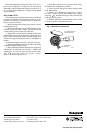
A current rating is usually stamped in the nameplate of
the primary control. Set the adjustable heat anticipator
indicator to match the value given on the nameplate.
If current rating is not available, proceed as follows to
determine the rating:
1. Turn off power.
2. Wire thermostat, except for connection to W terminal,
but do not mount it on the wall.
3. Connect the ammeter between W wire and W terminal
on the thermostat in series with the primary control.
4. Prepare the system for operation.
5. Turn on power.
6. Turn system switch to heat.
7. Increase thermostat setpoint as necessary to get system
operating.
8. With the system operating through the ammeter, wait
one minute, then read the ammeter.
9. Turn the system switch to OFF, and turn off power.
10. Adjust the heat anticipator to match the reading on
the ammeter.
11. Disconnect the ammeter, reconnect the W wire, and
mount the thermostat. Continue with system checkout.
NOTE: For best performance, the heat anticipator may
require further adjustment. To lengthen burner-on time,
move the indicator in the direction of the longer ar-
rows—not more than one-half scale marking at a time.
To shorten burner-on time, move indicator in opposite
direction.
Checkout
CAUTION
CAUTION
Do not check thermostat operation by shorting
across system control terminals. This damages the
thermostat heat anticipator.
IMPORTANT: The T822A,D,F, TS822A, and T8022D
can only be installed in heating applications. Per-
form only steps 1 and 2. The T822G can be installed
for either heating or cooling applications. If installed
for heating, perform steps 1 and 2. If installed for
cooling, perform step 6.
1. Set T822F FAN switch to AUTO. Fan operation is
controlled by the thermostat.
2. Move temperature setting lever about 10° F [6° C]
above room temperature.
• Gas or oil heating systems: heating starts immedi-
ately. Fan starts after short delay.
• Electric heating systems: heating and fan start imme-
diately.
3. Move temperature setting lever about 10° F [6° C]
below room temperature.
• Gas or oil heating systems: heating stops immedi-
ately. Fan stops after a short delay.
• Electric heating systems: heating and fan stop imme-
diately.
4. Set T822F FAN switch to ON. Fan runs continu-
ously.
5. Set temperature lever and T822F FAN switch to the
desired settings.
CAUTION
Do not operate T822G in cooling applications if
the outdoor temperature is below 50° F [10° C].
Refer to the air conditioner manufacturer’s
recommendations.
6. T822G COOLING APPLICATIONS ONLY:
NOTE: To prevent compressor short cycling, install a five
minute time delay. The time delay will not activate the
compressor for five minutes after the thermostat turns
off the compressor or for five minutes after the system
receives power.
CONNECT R AND W TERMINALS FOR 750 mV SYSTEMS. CONNECT
R AND Y TERMINALS FOR 250/500 mV SYTSEMS.
M1294
TS822A
TEMP. FALL
H1
R
Y
1
W
LIMIT
CONTROL
1
TH
TH/
PP
PP
MILLIVOLTAGE
GENERATOR
MILLIVOLTAGE
GAS CONTROL
PILOTSTAT
CONTROL
(IF USED)