


5 69-0638—1
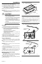
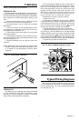
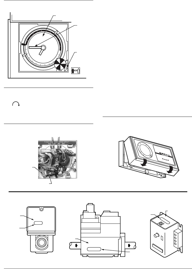
Fig. 8—Set clock.
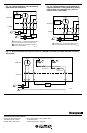
SET HEAT ANTICIPATOR
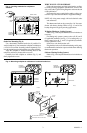
Adjust the heat anticipator lever to match the current
rating of the primary control for the proper cycle rate (Fig. 9).
Adjustable anticipation must be set for total current of
heat and fan control.
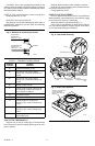
The current rating is usually stamped on the control or
valve (Fig. 10), or a setting may be given in the device
instructions.
If no current rating or heat anticipator setting is given,
measure the current with an ammeter. Proceed with the fol-
lowing steps.
Remove the thermostat from the wallplate or subbase.
Connect an ac ammeter of appropriate range (about 0A to
2A) between the R and W terminals on the wallplate or sub-
base except for electric heat and heat pump systems.
Let the system operate for one minute.
Adjust the heat anticipator lever to match the number that
reads on the ammeter.
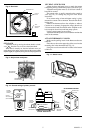
ATTACH THERMOSTAT COVER
Make sure the packing inserts in the thermostat base are
removed.
Place the two tabs on the upper edge of the cover into the
mounting slots in the thermostat base (Fig. 11).
Swing the cover downward until it catches at the bottom
of the base.
Fig. 11—Attach cover.
MINUTE
HAND
TIME
INDICATOR
ARROW
M1813A
PROGRAM DIAL
SET CLOCK
Adjust the clock by moving the minute hand in a clock-
wise direction. Do not reverse the minute hand.
When time is correctly set, the time indicator arrow (tri-
angle shape) points to the correct time and the corresponding
daytime (light) or nighttime (dark) portion of the program dial.
Fig. 9—Adjust heat anticipator.
M7317
ANTICIPATOR
SCALEPLATE
ANTICIPATOR
SETTING LEVER
Fig. 10—Current rating of primary control.
V8043E 1004 4
24V 50/60CY
.32 AMP
@ 60CY
8406
24 Vac 50/60 Hz
0.4 AMP
30 VAC
0.2 AMP
T
F
T
F
OIL BURNER CONTROL
SHOWS
CURRENT
DRAW
SHOWS LOW
VOLTAGE
M6116A
FROM MAIN
FUEL SUPPLY
SHOWS
VOLTAGE
RATING
TO
BURNER
SHOWS
ANTICIPATOR
SETTING
TYPICAL GAS VALVE
ZONE VALVE
SHOWS
VOLTAGE
RATING
SHOWS
ANTICIPATOR
SETTING
12
6
3
9
50
60
70
80
M1519