


VisionPRO
TM
8000 Touchscreen Programmable Thermostat
5 68-0280—01
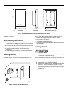
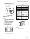
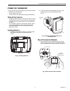
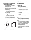
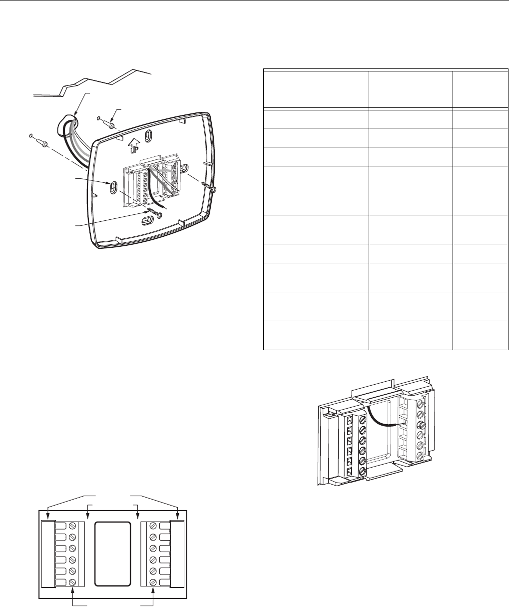
4. Position the wallplate over the holes, pulling wires
through the wiring opening. See Fig. 6.
5. Insert the mounting screws into the holes and tighten.
Fig. 6. Mounting wallplate.
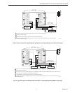
WIRING (FIG. 9 - 21)
All wiring must comply with local electrical codes and
ordinances.
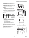
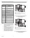
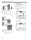
1. Select set of terminal identifications (Table 1) that
corresponds with system type (conventional or heat
pump in Fig. 7).
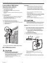
2. Loosen the screws for the appropriate system type
selected; see Table 1. See Table 2 for terminal
designation descriptions. Insert wires in the terminal
block under the loosened screw. See Fig. 8.
3. Securely tighten each screw.
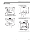
4. Push excess wire back into the hole.
5. Plug the hole with nonflammable insulation to prevent
drafts from affecting the thermostat.
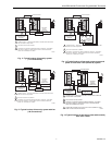
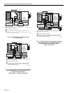
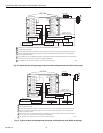
6. See Fig. 9 through 21 for typical wiring hookups.
Fig. 7. Selecting terminal identifications for
system type.
Fig. 8. Inserting wires in terminal block.
IMPORTANT
Use 18 gauge thermostat wire.
WALL
MOUNTING
HOLES
M19916
MOUNTING
SCREWS (2)
WALL ANCHORS (2)
WIRES THROUGH WALL
AND WIRE SLOT
CO
NVENTI
O
NA
L
SC
REW TERMINAL
S
H
EAT P
UMP
M19951
Y2
L
E
AUX
S1
S2
Y2
W2
S1
S
2
RC
R
O/B
Y
G
C
R
C
R
W
Y
G
C
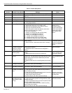
Table 1. Selecting Terminal Identifications for
System Type.
System Type
Wallplate
Terminal
Identifications
Wiring
Diagram
Reference
Standard Heat/Cool Conventional 9, 10
Heat Only Conventional 11
Heat Only with Fan Conventional 12
Heat Only (Series 20)
Power to open and
power to close zone
valves
Conventional 13
Normally Open Zone
Valves—Heat Only
Conventional 14
Cool Only Conventional 15
Standard Multistage up
to 2 Heat/2 Cool
Conventional 16, 17
Heat Pump with No
Auxiliary Heat
Heat Pump 18, 19
Heat Pump with
Auxiliary Heat
Heat Pump 20, 21
M19917