


VisionPRO
TM
8000 Touchscreen Programmable Thermostat
68-0280—01 12
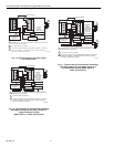
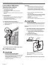
Locate and Mount C7089U Outdoor
Temperature Sensor (Optional)
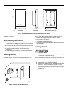
Mount the sensor where (see Fig. 25):
• cannot tamper with settings.
• there is good air circulation.
• it can measure true outdoor ambient temperature.
• surface is flat.
• wire distance between C7089 and thermostat is less than
200 feet.
Do not mount the sensor:
• in direct sunlight.
• where hot or cold air blows on the sensor. Discharge line
from an outdoor compressor unit, vent or fan causes
inaccurate temperature readings.
• where snow, ice or debris can cover it.
Use the following steps to mount the sensor:
1. Remove the sensor from the mounting clip.
2. Mark the area on the location selected for mounting the
sensor mounting clip.
3. Mount the clip.
Fig. 25. Typical locations for C7089U Outdoor Sensor.
Wire C7089U Outdoor Sensor
CAUTION
Electrical Interference (Noise) Hazard.
Can cause erratic system operation.
Keep wiring at least one foot away from large inductive
loads such as motors, line starters, lighting ballasts
and large power distribution panels.
Use shielded cable to reduce interference when
rerouting is not possible.
IMPORTANT
Erratic temperature readings from a sensor can
occur as a result of any of the wiring practices
described below. Avoid these practices to assure
correct operation. Use shielded cable to reduce
interference if rerouting sensor wiring is not possible.
— Be sure wires have a cable separate from the
thermostat cable.
— Do not route temperature sensor wiring with building
power wiring, next to control contactors or near light
dimming circuits, electric motors or welding
equipment.
— Avoid poor wiring connections.
— Avoid intermittent or missing building earth ground.
CAUTION
Electrical Shock Hazard.
Can cause electrical shock or equipment damage.
Disconnect power supply before connecting wiring.
Wiring must comply with applicable codes, ordinances and
regulations:
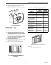
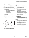
1. Wire C7089 Outdoor Sensor to S1and S2 terminals on
the thermostat. If leadwire provided is not long enough
(60 in.), run a cable to a hole at C7089 location.
a. Using color-coded, 18-gauge thermostat wire is
recommended. For example of general wiring of
C7089, see Fig. 26.
b. Pigtail wiring can be used.
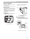
2. Mount C7089 in its mounting clip.
3. Plug wiring hole using nonhardening caulk or putty.
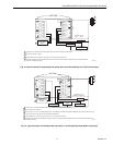
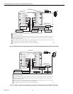
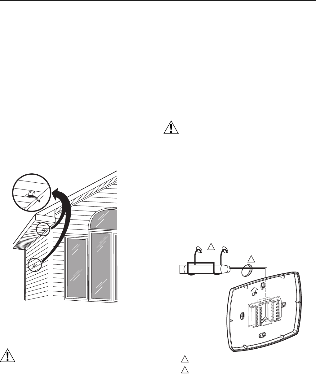
Fig. 26. Wire C7089 Outdoor Sensor to the thermostat.
M7514
1
2
2
1
USE APPROPRIATE MOUNTING MEANS FOR THE
TYPE OF STRUCTURE.
PLUG WIRING HOLE WITH NON-HARDENING CAULK
OR PUTTY.
C7089
WIRING HOLE
THROUGH
STRUCTURE
M19970