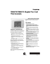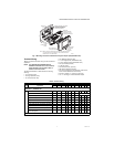
TB6575/TB8575 DIGITAL FAN COIL THERMOSTATS
62-0311—13 6
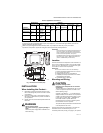
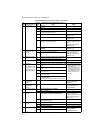
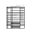
Terminal Identifier
LW/Y n/a
i
Gl Gm Gh N Rs
a
Sc
b
SB
c
Ps
d
Fly lead wire color
Black Orange Red Blue Brown White None
e
2 pipes; Heat only W
ORO
2 pipes; Cool only Y
ORO
2 pipes; Heat or Cool with Manual Changeover W/Y
ORO
2 pipes; Heat or Cool with Seasonal Changeover W/Y
ORO
TB8575A1016 — 24 Vac
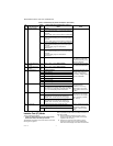
Terminal Identifier
j
RW/YY/AGlGmGhCRs
a
Sc
b
SB
c
Ps
d
2 pipes; Heat only W
ORO
2 pipes; Cool only Y
ORO
2 pipes; Heat or Cool with Manual Changeover W/Y
ORO
2 pipes; Heat or Cool with Seasonal Changeover W/Y
ORO
4 pipes; Heat and Cool with Manual Changeover WY
ORO
4 pipes; Heat and Cool with Auto Changeover WY
ORO
2 pipes; Heat or Cool with Auxiliary Heat W/Y A
ORO
4 pipes; Heat and Cool with Manual Changeover
or Auto Changeover
WY
ORO
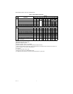
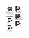
a
Rs; Remote sensor is optional.
b
Required when Rs, SB, or Ps is wired.
c
SB; Remote setback is optional.
d
Pipe sensor: Discrete, Analog, or Aquastat®.
e
These terminals (8, 9, 10, and 11) do not have lead wires attached to them.
f
A check mark (ü) indicates the terminal is used in that application. Rs and SB terminal connections are optional. If a
terminal is left blank, it is not used in that application.
g
O = Optional
h
R = Required if Rs, SB, or Ps is wired.
i
Terminal 3 is not used on the TB6575B1000 model.
j
The TB8575A1016 model does not have fly lead wires attached to any terminals.
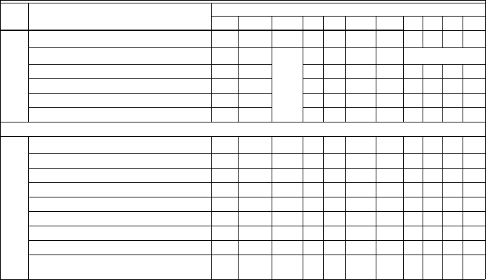
Table 3. Terminal Wiring. (Continued)
Model Application
Terminals
1234567891011


