


TB6575/TB8575 DIGITAL FAN COIL THERMOSTATS
5 62-0311—13
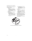
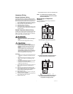
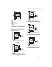
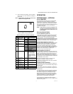
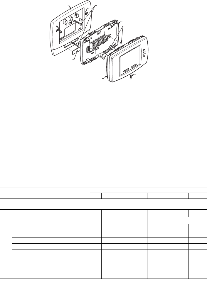
Fig. 3. Mounting sub-base and thermostat using the adaptor plate (50033847-001).
Terminal Wiring
Table 3 provides the terminal wiring for each model and
application.
NOTE: The TB6575A1016,TB6575B1000 and
TB6575C1016 models have color coded fly
leads attached to the terminals. Refer to
Table 3 for the color codes.
The Terminal Identifiers in Table 3 have the following
meaning:
• C: Common 24 Vac
• Gh: High speed fan relay
• Gl: Low speed fan relay
• Gm: Medium speed fan relay
• L: Line voltage power (120/240/277 Vac)
• N: Line voltage ground (120/240/277 Vac)
• Ps: Pipe sensor (optional)
• R: 24 Vac power
• Rs: Remote sensor (optional)
• SB: Remote setback (optional)
• Sc: Ground (required if remote sensor, pipe sensor,
and/or remote setback are connected)
• W/Y: W = Heating; Y = Cooling (2 pipe only)
• Y/A: Y = Cooling; A = Electrical heater output
M27591
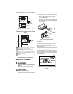
INSERT SCREW
TO LOCK MAIN
BODY TO
SUB-BASE
SNAP MAIN BODY
ONTO SUB-BASE
SUB-BASE
MOUNT ADAPTOR PLATE ONTO
4X4 WIRING BOX OR 2X4
VERTICAL JUNCTION BOX
USING TWO SCREWS
ADAPTOR
PLATE
SCREW HEAD
COVER
ADAPTOR
PLATE
MOUNT SUB-BASE
ONTO WALL PLATE
USING TWO SCREWS
NOTE: MIDDLE HOLES OF ADAPTOR PLATE ARE USED FOR MOUNTING
TO A 2X4 VERTICAL JUNCTION BOX. USE OUTER HOLES FOR
MOUNTING TO A 4X4 WIRING BOX.
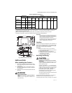
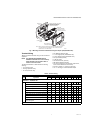
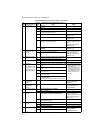
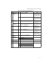
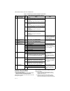
Table 3. Terminal Wiring.
Model Application
Terminals
1234567891011
TB6575A1016 — 120/240 Vac;
TB6575C1016 — 120/240/277 Vac
Terminal Identifier
LW/Y Y/AGlGmGhNRs
a
Sc
b
SB
c
Ps
d
Fly lead wire color
Black Orange Yellow Red Blue Brown White None
e
2 pipes; Heat only
f
W
O
g
R
h
O
2 pipes; Cool only Y
ORO
2 pipes; Heat or Cool with Manual Changeover W/Y
ORO
2 pipes; Heat or Cool with Seasonal Changeover W/Y
ORO
4 pipes; Heat and Cool with Manual Changeover WY
ORO
4 pipes; Heat and Cool with Auto Changeover WY
ORO
2 pipes; Heat or Cool with Auxiliary Heat W/Y A
ORO
4 pipes; Heat and Cool with Manual Changeover
or Auto Changeover
WY
ORO
TB6575B1000 — 120/240 Vac