


English: Page 1 • Français : Page 6 • Español: Página 11
3
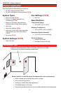
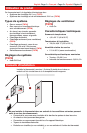
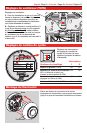
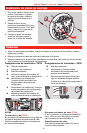
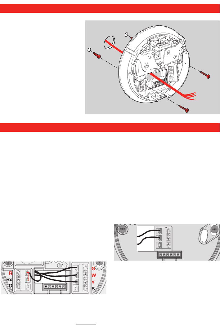
1. Pull wires through wire
hole. Position wallplate on
wall, level, and mark hole
positions.
2. Drill holes (3/16” for drywall,
7/32” for plaster) and tap in
supplied wall anchors.
3. Pull wire through wallplate,
position over anchors, then
insert and tighten mounting
screws. Check level if
desired.
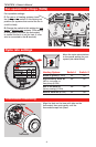
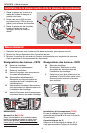
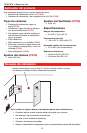
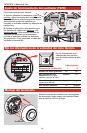
1. Loosen screw terminals, insert wires into terminal block, then re-tighten screws.
2. Push excess wire back into the wall opening.
3. Plug the wall opening with nonflammable insulation to prevent drafts from affecting
thermostat operation.
Wiring
NOTES
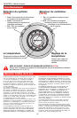
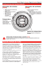
R & Rc terminals (T87N)
In single-transformer system, leave metal
jumper in place between R & Rc. Remove
metal jumper if two-transformer system.
Heat pump systems (T87N)
If wiring to a heat pump, use a small piece
of wire (not supplied) to connect terminals W
and Y.
Wire specifications
Use 18-gauge thermostat wire. Shielded cable
is not required.
Wallplate installation
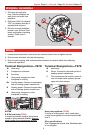
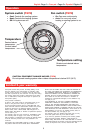
Terminal Designations—T87N
W Heat relay.
Y Compressor contactor.
G Fan relay.
O Heat pump changeover valve
energized in cooling.
Rc Cooling power. Connect to secondary
side of cooling system transformer.
R Heating power. Connect to secondary
side of heating system transformer.
B Heat pump changeover valve
energized in heating.
Terminal Designations—T87K
W Heat relay.
R Power. Connect to secondary side of
heating system transformer.
Y This terminal can be used for some 3-
wire hot-water valve systems (power
open and close valves).
R
W
Y