


T87F THERMOSTATS
60-2222—3 G.H. Rev. 8-02 www.honeywell.com/yourhome
Automation and Control Solutions
Honeywell Honeywell Limited-Honeywell Limitée
1985 Douglas Drive North 35 Dynamic Drive
Golden Valley, MN 55422 Scarborough, Ontario
M1V 4Z9
Printed in U.S.A. on recycled
paper containing at least 10%
post-consumer paper fibers.
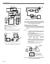
IMPORTANT
When the T87F is used in a series 20 heating circuit
(requires contact on both a rise and fall in tempera-
ture), set the anticipator indicator to 1.2.
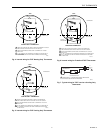
If the current rating is not known, proceed as follows:
1. Connect an ac ammeter of appropriate range (for exam-
ple; 0 to 2A) between the R and W terminals on the
wallplate, or between R and W on the subbase.
2. Let the system operate through the ammeter for at least
one minute before taking the reading.
3. Set the heat anticipator to correspond to the ammeter
reading (see Fig. 15).
4. A slightly higher setting to obtain longer burner-on times
(and fewer cycles per hour) may be desirable in sys-
tems such as a one-pipe steam system. For example:
• if burner on-time is too short with a heater setting of
0.4, adjust to the 0.45 setting and check the system
operation, then
• adjust to the 0.5 setting and recheck until the desired
burner-on time is obtained.
OPERATION
CAUTION
Equipment Damage Hazard.
Improper installation can burn out thermostat heat
anticipator.
On systems using a low voltage gas valve, do not
apply a jumper across the valve coil terminals.
To check thermostat operation:
1. Turn down the temperature setting to the lowest point.
2. If the subbase is used, move the system switch to the
HEAT position.
3. Raise the temperature setting until the burner starts.
4. Slowly turn the dial back. (The burner should stop when
the dial has been turned down below the room tempera-
ture.)
5. If the T87F controls cooling, move the subbase system
switch (if used) to COOL and lower the setting until the
cooling equipment starts.
6. Raise the setting above the room temperature and the
cooling system should shut down.
7. Make certain that the equipment functions properly in
response to the thermostat.
RECALIBRATION
IMPORTANT
— If the thermostat scaleplate moves (pointer is station-
ary) when setting the temperature, the thermostat is
a Group I model.
— If the scaleplate is stationary and the pointer moves,
the thermostat is a Group II model.
The T87F is accurately calibrated at the factory under
controlled conditions and no recalibration should be
necessary. If it appears that the thermostat is out of
calibration, make sure that it is level and is not subjected to
radiant heat from the sun, radiators, or appliances.
Remove the thermostat cover ring so you can observe the
mercury switch action. After a five- or ten-minute off-period
(with thermostat setting below the room temperature), slowly
raise the setting until the switch just makes contact. If the
thermometer pointer and setting indicator read the same the
instant you see the switch make, no recalibration is
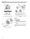
necessary. If recalibration is necessary, proceed as follows:
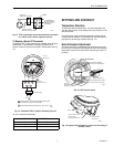
1. Turn the setting dial a few degrees above the room tem-
perature and remove the cover.
2. Slip the 104994 Calibration Wrench (available on
request) onto the hex under the bimetal coil (see Fig.
14).
3. Hold the dial firmly, and turn the hex counterclockwise
for Group I models and clockwise for Group II models,
until the mercury breaks contact.
4. Turn the dial to a low setting so that the thermostat
loses the heat it has gained from your hands and its
own operation.
5. Wait at least five minutes.
6. Slowly turn the dial until the pointers read the same.
7. Firmly hold the dial—carefully turning the hex clockwise
for Group I models, counterclockwise for Group II mod-
els—until the mercury switch slips to the heating contact
end of the tube.
8. Recheck the calibration, select the desired temperature
and replace the cover.
NOTE: When the T87F provides cooling control, calibration
for heating automatically calibrates for cooling.