


T87F THERMOSTATS
3 60-2222—3
Accessories:
Q539 Subbases—provide system and fan switching and cool-
ing anticipation (unless otherwise specified) for T87F heat-
ing, cooling and heating-cooling thermostats.
TG587F1008 Thermostat Guard Key Lock Cover with window.
TG587F1016 Thermostat Guard Key Lock cover without
window.
104456B Two terminal heat only T87 Wallplate.
137421AE-T87 Taupe Wallplate with positive Off.
137421K-T87 Taupe Wallplate without positive Off.
137421R-T87 White Wallplate.
198170A Designer Beige Adapter Kit.
198172 Cover Ring for T87 Designer Beige models.
199933 Cover Ring for Taupe T87 models.
114855-00029 Cover Ring for Gold T87 models.
137421A-T87 Gold Wallplate without positive Off.
137421B-T87 Gold Wallplate with positive Off.
221886A Easy-to-Use™ Clear Ring. Durable plastic ring
snaps on Easy-to-See models.
202687A Premier White® Adapter Kit includes 6 in. cover
assembly and adapter ring to mount on outlet box or cover
marks from old thermostats.
32005439-001 Taupe Adapter Kit includes 6 in. cover assem-
bly and adapter ring to mount on outlet box or cover marks
from old thermostat.
MERCURY NOTICE
If this control is replacing a control that contains
mercury in a sealed tube, do not place your old control
in the trash. Dispose of properly.
Contact your local waste management authority for
instructions regarding recycling and the proper
disposal of an old control.
INSTALLATION
CAUTION
Voltage Hazard.
Can cause electrical shock or equipment damage.
Disconnect power before beginning installation.
CAUTION
Equipment Damage Hazard.
Improper installation can burn out thermostat heat
anticipator.
On systems using a low voltage gas valve, do not
apply a jumper across the valve coil terminals.
When Installing this Product. . .
1. Read these instructions carefully. Failure to follow them
could cause a hazardous condition.
2. Check the ratings given in the instructions and on the
product to make sure the product is suitable for your
application.
3. Installer must be a trained experienced service techni-
cian.
4. After installation is complete, check out product opera-
tion as provided in these instructions.
Location
Locate the thermostat about 5 ft (1.5m) above the floor in an
area with good air circulation at average temperature.
Do not install the thermostat where it can be affected by:
— drafts, or dead spots behind doors and in corners.
— hot or cold air from ducts.
— radiant heat from sun or appliances.
— concealed pipes and chimneys.
— unheated (uncooled) areas such as an outside wall behind
the thermostat.
This thermostat is a precision instrument and was carefully
adjusted at the factory. Handle it carefully.
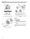
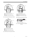
Mount Wallplate or Subbase
IMPORTANT
Use a spirit level to accurately level the wallplate or
subbase as shown in Fig. 1. Inaccurate leveling may
cause the thermostat to deviate from setpoint.
When using the T87F with a Q539 Subbase, follow
the mounting and wiring instructions for the subbase.
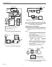
Use the cover ring (if desired), adapter plate (if needed),
wallplate or subbase, T87F and screws as shown in Fig. 2 and
3.
IMPORTANT
Before mounting the thermostat, see Setting and
Checkout section, Heat Anticipator Adjustment sub-
section.
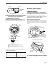
1. Place the cover ring on the wall at the desired location
with the cable entrance holes to the left.
NOTE: If an outlet box is used, place the cable entrance
holes toward the bottom. The side showing MADE IN
U.S.A. must be against the wall.
2. Pull the thermostat cable through the entrance hole of
the cover ring and the entrance hole of the wallplate or
subbase and adapter plate (if used).
3. Fasten the cover ring, adapter plate (if used), and the
wallplate or subbase.
4. Level the wallplate as shown in Fig. 1 and tighten the
screws.
5. After wiring the subbase or wallplate, plug the hole to
prevent interior wall drafts from affecting the thermostat.
6. Align the thermostat over the wallplate and tighten the
three captive mounting screws.