Disconnect power before wiring to prevent electrical
shock or equipment damage.
The shape of the terminal barrier permits insertion of
straight or conventional wraparound wiring connections.
Either method is acceptable.
Refer to Figs. 3-5 for typical hookups of subbase and
thermostat.
NOTE: Keep all wiring restricted to ribbed area surround-
ing terminals to assure thermostat/subbase contact. See
Fig. 6.
MOUNTING SUBBASE
The subbase does not require leveling for proper opera-
tion, but only for appearance.
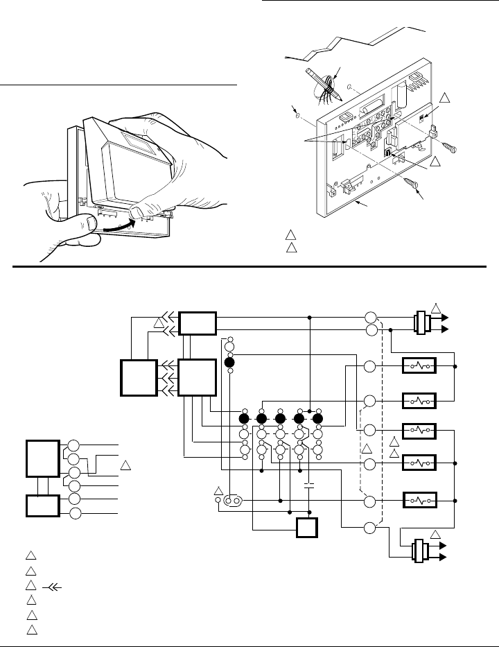
Remove thermostat from subbase. See Fig. 1.
The subbase mounts directly onto the wall with the
screws and anchors included in the package. Use the
subbase as a template, and with a pencil, mark the two
mounting screw positions. See Fig. 2. If drywall construc-
tion, plastic anchors must be used; select 3/16 in. bit to
drill holes for anchors. Gently tap anchors into holes until
they are flush with the wall surface. Thread wires through
the center opening of the subbase. Then, mount the subbase
by using two screws provided. Gently tighten screws, level
top surface of subbase and then securely tighten screws.
WIRING
All wiring must comply with local electrical codes and
ordinances.
Fig. 1—Removing thermostat from subbase.
AUX. HEAT
HEAT
AUTO
COOL
OFF
O
N
A
U
T
O
F
A
N
M3060
S
Y
S
T
E
M
Fig. 2—Mounting subbase on wall.
WIRES THROUGH
WALL OPENING
WALL
WALL
ANCHORS
(2)
SUBBASE
MOUNTING
HOLES
MOUNTING
SCREWS (2)
M3061
HBUS
SWITCH
FAN
OPERATIONAL
SWITCH FOR
T8631A ONLY
1
2
1
2
SWITCH UP DISCONNECTS THE HBUS.
FAN CAN BE SET FOR ELECTRIC HEAT OR CONVENTIONAL.
Fig. 3—T8631A 1-stage heat/1-stage cool thermostat with HEAT-OFF-COOL system and ON-AUTO fan
switching.
2
AUTO
ON
FAN
SWITCH
POWER
SUPPLY
COOL
HEAT
SYSTEM
SWITCH
OFF
SUBBASE
LOGIC/
CONTROL
CIRCUIT
STAT
LOGIC
CIRCUIT
HEAT/
COOL
HIGH
LIMIT
B
W
O
RC
L2
2
COOL DAMPER OR
CHANGEOVER RELAY
C
HEAT RELAY
G
FAN RELAY
R
Y
HEAT DAMPER OR
CHANGEOVER RELAY
L1
(HOT)
5
BUS IN
POWER
SUPPLY
TRANS-
CEIVER
BUS OUT
BUS
POWER
SUPPLY
+
_
13.7 VDC
H2
H1
H3
H3
H4
H4
4
POWER SUPPLY. PROVIDE DISCONNECT MEANS AND OVERLOAD PROTECTION AS REQUIRED.
JUMPER R AND RC FOR SINGLE TRANSFORMER SYSTEM.
DENOTES THERMOSTAT TO SUBBASE INTERCONNECT.
DO NOT CONNECT H BUS WIRES TO THERMOSTAT UNTIL OTHER TotalHome DEVICES ARE CONNECTED.
FAN OPERATION SWITCH (4A) IN ELEC. POSITION, USE ONE SYSTEM TRANSFORMER AND JUMPER R TO RC.
FOR SINGLE STAGE HEAT PUMP APPLICATIONS, JUMPER W TO Y FOR SINGLE COMPRESSOR CONTACTOR
OPERATION.
1
4
2
3
M3066A
L2
L1
(HOT)
COMPRESSOR
CONTACTOR
COOLING
SYSTEM
TRANSFORMER
HEATING SYSTEM
TRANSFORMER
1
5
5
3
1
ELEC.
CONV.
6
6


