T8631A,R Communicating
Chronotherm III Thermostats
J.H . • Rev. 3-93 • © Honeywell Inc. 1993 • Form Number 69-0689—2
Application
T8631A,R can be connected to Honeywell's TotalHome
system for external access and control. TotalHome system
devices communicate using HBus, a Honeywell communi-
cations protocol.
These thermostats, powered directly from the control
transformer, provide energy saving control for a 24 Vac
conventional heating/cooling or multistage heat pump
heating/cooling system as indicated in Table 1.
As long as AC power is continuously available to the
transformer, the thermostat will be compatible with most
control systems.
The T8631A,R models include a SYSTEM LED near
the top of the thermostat face. The SYSTEM LED lights
when the thermostat is signaling for heating or cooling.
T8631R includes AUX. HT. and EM. HT LEDs near the
bottom center of the subbase. The AUX. HT. LED lights
whenever the thermostat is calling for operation of the
backup or auxiliary heater. Backup (auxiliary) heat is more
expensive to operate than the heat pump and typically is
used only when the heat pump is unable to handle the load.
The EM. HT. LED lights whenever the thermostat system
switch is in the EM. HT. position. The EM.HT. LED may
also light on some systems if the heat pump is malfunction-
ing. The system switch needs to be moved to EM.HT. on
these heat pumps.
Heat and cool anticipation is fixed in both models; no
adjustment is necessary. T8631A has adjustable cycle rate
for heating; T8631R cycle rate is adjustable only for
auxiliary heat.
Installation
WHEN INSTALLING THIS PRODUCT…
1. Read these instructions carefully. Failure to follow
them could damage the product or cause a hazardous
condition.
2. Check the ratings on the product to make sure the
product is suitable for your application.
3. Installer must be a trained, experienced service tech-
nician.
4. After installation is complete, check out product
operation as provided in these instructions.
5. Allow thermostat to warm to room temperature
before operating.
IMPORTANT: After wiring is complete, push excess wire
back into the hole, and plug hole with nonhardening
caulk, putty or insulation to prevent drafts from
affecting thermostat operation.
LOCATION
Install thermostat and subbase about 5 ft [1.5 m] above
the floor in an area with good air circulation at room
temperature.
Do not install the thermostat where it may be affected by:
— drafts or dead spots behind doors, in corners or under
cabinets.
— hot or cold air from ducts.
— radiant heat from sun or appliances.
— concealed pipes and chimneys.
— unheated (uncooled) areas behind the thermostat,
such as an outside wall.
WIRING TO HEATING/COOLING SYSTEM
The T8631 requires connection to both sides of the
heating transformer secondary for power.
If Replacing An Existing Thermostat
Turn off power to thermostat at furnace or heat pump.
A two-transformer system may require turning off two
switches or disconnects. Remove any existing wallplate or
subbase from wall. Label each wire with, or write down,
the letter or number on the wiring terminal as the wire is
removed, to avoid miswiring later.
If New Installation
Run cable to a hole at the selected wall location, and
pull about 3 in. [76 mm.] of wire through the opening.
Color-coded, 18-gauge thermostat cable with one conduc-
tor for each wiring terminal, excluding H terminals, is
recommended. Good service practice recommends select-
ing cable with one or two more conductors than the
immediate application requires.
WIRING TO TOTALHOME SYSTEM
The HBus connection requires an unshielded cable with
3 twisted pairs of #22 AWG solid wire. Use Belden #8742,
Alpha #1304 or equivalent wire. Route this cable with the
thermostat cable to the utility room. Do not connect the
HBus cable to the T8631 until the other TotalHome devices
are connected.
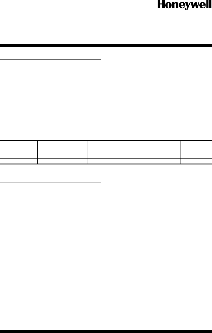
TABLE I—THERMOSTAT MODELS.
Stages Switching
Thermostat Heat Cool System Fan Program
T8631A 1 1 HEAT-OFF-COOL ON-AUTO 5-1-1
T8631R 2 1 EM. HT.-HEAT-OFF-COOL ON-AUTO 5-1-1


