


T8624D CHRONOTHERM
®
IV DELUXE PROGRAMMABLE THERMOSTAT
68-0166—1
5
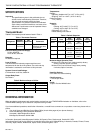
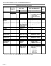
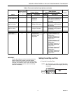
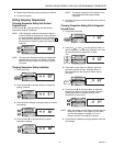
Table 4. Terminal Designations and Descriptions.
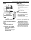
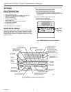
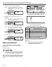
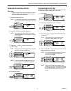
Fig. 4. Proper wiring technique.
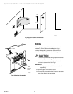
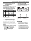
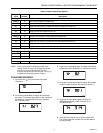
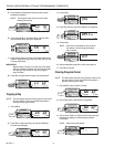
Mounting Thermostat Wallplate
The thermostat mounts on the wallplate after they are
installed.
1. Engage tabs at the top of thermostat and wallplate.
See Fig. 5.
2. Press lower edge of case to latch.
NOTE: To remove the thermostat from the wall, first pull out
at the bottom of the thermostat; then remove the top.
Fig. 5. Mounting thermostat on wallplate.
Standard
Terminal
Designations
Alternate
Terminal
Designations Typical Connection Function Terminal Type
B—Heat damper or changeover valve Output 24V powered contact
CB
a
, C, X1, X2 Common Input
GF Fan relay Output 24V powered contact
ORCool damper or changeover valve Output 24V powered contact
OT, OT — Outdoor temperature sensor (C7089B) Input —
RV24V system or heating transformer Input —
RC — 24V cooling transformer Input —
W1 H1, R3 Stage 1 heating relay Output 24V powered contact
W2 H2, R4, W3, Y Stage 2 heating relay Output 24V powered contact
Y1 C1, M, Y Stage 1 compressor contactor Output 24V powered contact
Y2 C2, M, Y Stage 2 compressor contactor Output 24V powered contact
a
Some OEM models label the terminal for transformer common B.
M4826
FOR WRAPAROUND
INSERTION STRIP
7/16 IN. (11 MM).
FOR STRAIGHT
INSERTION STRIP
5/16 IN. (8 MM).
M15043
B.
PRESS LOWER EDGE OF CASE TO LATCH.
A.
ENGAGE TABS AT TOP OF THERMOSTAT AND WALLPLATE.