


5 69-0330—3
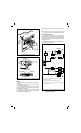
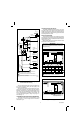
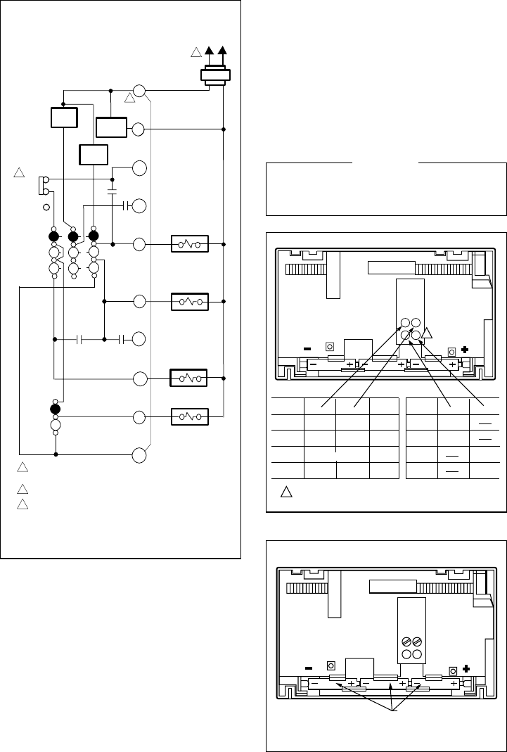
Fig. 9—T8621D single-stage manual changeover heat
pump thermostat. HEAT-OFF-COOL system
and AUTO-ON fan switching.
The room air temperature will normally vary slightly from
the comfort temperature setting with the cycling of the
furnace or air conditioner.
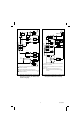
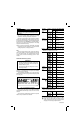
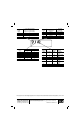
The heating cycle rate of this thermostat is factory-set for
gas/oil warm air heating. The cooling cycle rate cannot be
adjusted. The heating cycle rate can be adjusted by turning
one or both cycle rate adjustment screws located on the
back of the thermostat. In multistage heat systems, the
cycle rate adjustment applies to stage 2 only; stage 1 is
fixed. See Fig. 10.
TIME/TEMPERATURE CONVERSION (SOME MODELS)
The display readout may be converted between 12 and
24 hour clock or °C and °F using screws 2A and 2B as
indicated in Fig. 10.
FAN OPERATION OPTION SWITCH
The SUPER TRADELINE model includes a fan opera-
tion option switch on the subbase, visible before the ther-
mostat is mounted on the subbase. The switch should be in
electric heat position for electric heating systems that do not
have independent fan control.
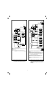
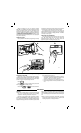
INSTALLING BATTERIES
Three AAA alkaline batteries are provided as backup to
prevent program loss in case of power outage. Batteries are
included with thermostat. Install batteries in back of thermo-
stat as shown in Fig. 11.
Without battery backup, the program will remain about
30 seconds in event of power loss.
IMPORTANT
When batteries are first installed, the display will flash
1:00 PM and 32° or 0°. The temperature display will
stay at 32° or 0° until the thermostat is powered from
the system wiring.
Fig. 11—Battery placement.
Fig. 10—Cycle rate adjustment.
M1546A
SYSTEM
TRANSFORMER
R
C
W1
W2
B
HEATING
CHANGEOVER
RELAY
O
Y2
Y1
G
RC
COMPRESSOR
CONTACTOR
FAN RELAY
HEAT 2
HEAT 1
HIGH
LIMIT
HIGH
LIMIT
L1
(HOT)
L2
HEAT
OFF
COOL
SYSTEM
SWITCH
COOL 1 COOL 2
AUTO
ON
FAN
SWITCH
NON-ELECTRIC
ELECTRIC
POWER SUPPLY. PROVIDE DISCONNECT MEANS AND
OVERLOAD PROTECTION AS REQUIRED.
FAN OPERATION SWITCH MAY BE IN EITHER POSITION.
1
2
NOMINAL 24 VAC POWER MUST BE PRESENT BETWEEN R AND C
FOR THERMOSTAT OPERATION.
FAN
OPERATION
SWITCH
2
3
1
3
POWER
SUPPLY
COOLING
CHANGEOVER
RELAY
SYSTEM
GRAVITY
AIR/WATER
HOT
WATER
GAS/OIL
WARM AIR
ELECTRIC
WARM AIR
1A
OUT 1/2
TO 1 TURN
OUT 1/2
TO 1 TURN
OUT 1/2
TO 1 TURN
OUT 1/2
TO 1 TURN
1B
IN
IN
(FACTORY SETTING)
IN IN
TIME/TEMP
DISPLAY
2A
2B
24 HR
IN
12 HR
o
o
C
F
OUT 1/2
TO 1 TURN
OUT 1/2
TO 1 TURN
IN
M311A
1 SCREWS 2A, 2B ONLY AVAILABLE ON SOME MODELS.
1A
2A 2B
1B
1
CYCLES
PER HOUR
1
3
6
9
BATTERY PLACEMENT
(NOTE CORRECT PLUS
AND MINUS DIRECTION)
M372A