


2
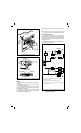
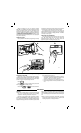
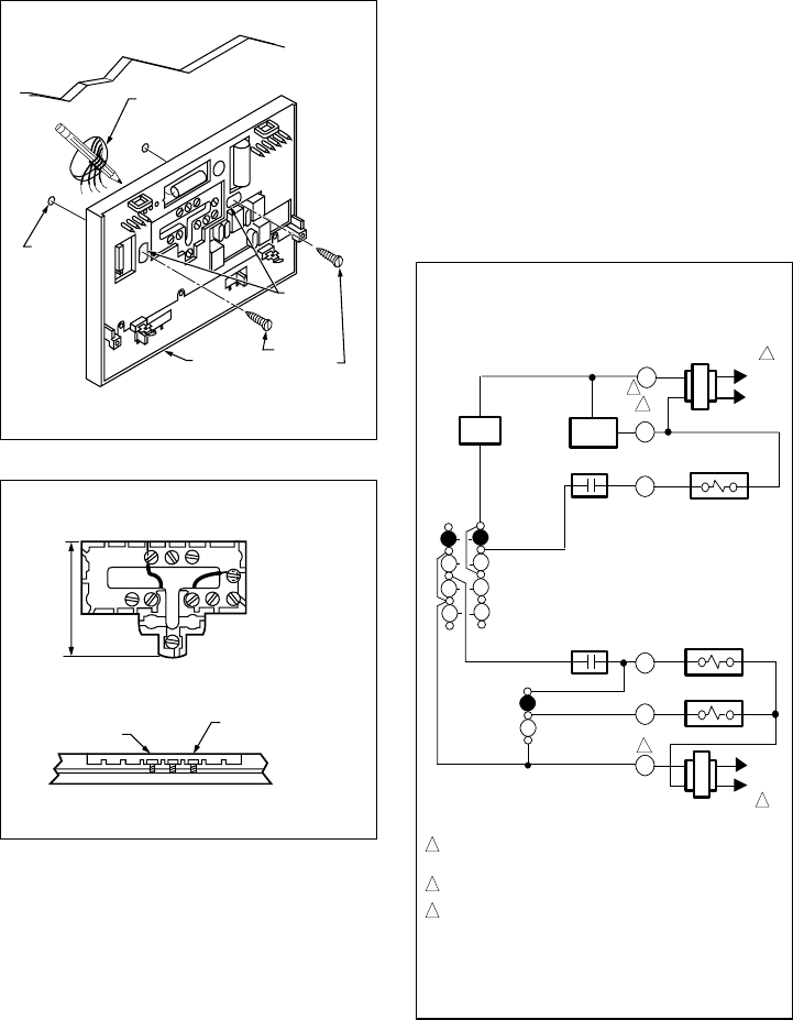
Fig. 2—Mounting subbase on wall.
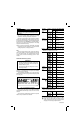
Fig. 3—Restrict wiring to recessed area surrounding
terminals.
WIRING
All wiring must comply with local electrical codes and
ordinances.
Disconnect power before wiring to prevent electrical
shock or equipment damage.
The shape of the terminal barrier permits insertion of
straight or conventional wraparound wiring connections.
Either method is acceptable.
Push excess wire back into the hole, and plug hole with
nonhardening caulk, putty or insulation to prevent drafts
from affecting thermostat operation.
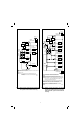
Refer to Figs. 4-9 for typical hookups of subbase thermo-
stat.
NOTE: Restrict all wiring to recessed area surrounding
terminals (Fig.3) to assure thermostat/subbase contact.
ADJUSTING CYCLE RATE
To custom-tailor the thermostat’s cycling performance
to different types of heating equipment, cycle rate adjust-
ment screws are provided on the back of the thermostat.
Correct setting of these screws will provide optimum room
temperature control.
NOTE: MOST APPLICATIONS WILL NOT REQUIRE A
CHANGE IN CYCLE RATE.
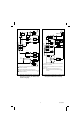
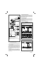
Fig. 4—T8621A 1-stage heat/1-stage cool thermostat
with HEAT-AUTO-COOL-OFF system and
AUTO-ON fan switching.
WIRES THROUGH
WALL OPENING
WALL
WALL
ANCHORS
(2)
SUBBASE
MOUNTING
HOLES
MOUNTING
SCREWS (2)
M846
FOR STRAIGHT
INSERTION –
STRIP 5/16 in. (8 mm)
FOR WRAPAROUND –
STRIP 7/16 in. (11 mm)
RESTRICT
WIRING TO
THIS AREA
KEEP WIRING BELOW
THIS SURFACE
TOP SURFACE
OF SUBBASE
FRONT VIEW OF
TERMINAL AREA
CROSS-SECTIONAL VIEW OF
TERMINAL AREA
M847
M1574
HEATING
TRANSFORMER
R
C
W1
HEAT RELAY
COOLING
TRANSFORMER
Y1
G
RC
COOLING
CONTACTOR
FAN RELAY
HIGH
LIMIT
L1
(HOT)
L2
HEAT
AUTO
OFF
SYSTEM
SWITCH
AUTO
ON
FAN
SWITCH
1 POWER SUPPLY. PROVIDE DISCONNECT MEANS AND OVERLOAD
PROTECTION AS REQUIRED.
FOR SINGLE TRANSFORMER SYSTEM JUMPER R AND RC.
NOMINAL 24 Vac POWER MUST BE PRESENT BETWEEN R AND C FOR
THERMOSTAT OPERATION.
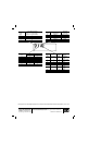
COOL
H
POWER
SUPPLY
2
1
C
L1
(HOT)
L2
1
2
3
2
3