


69-1567
2
T8602C CHRONOTHERM
®
IV DELUXE PROGRAMMABLE THERMOSTATS
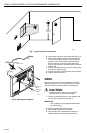
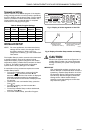
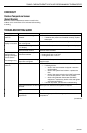
Fig. 1. Typical location of thermostat.
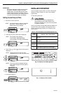
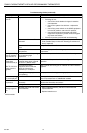
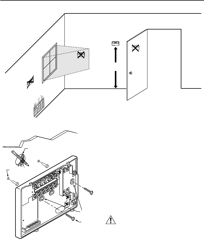
2. Use a pencil to mark the mounting holes. See Fig. 2.
3. Remove the wallplate from the wall and drill two
4.76 mm (3/16 inch) holes in the wall (if drywall)
as marked. For firmer material such as plaster,
drill two 5.56 mm (7/32 inch) holes. Gently tap
anchors (provided) into the drilled holes until flush
with the wall.
4. Position the wallplate over the holes, pulling wires
through the wiring opening.
5. Loosely insert the mounting screws into the holes.
6. Tighten mounting screws.
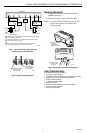
WIRING
All wiring must comply with local electrical codes and
ordinances. Refer to Fig. 3 for typical hookup. A letter
code is located near each terminal for identification.
CAUTION
Disconnect power before wiring to prevent
electrical shock or equipment damage.
1. Loosen the terminal screws on the wallplate and
connect the system wires. See Fig. 4.
IMPORTANT
Use 18 gauge, color-coded thermostat cable
for proper wiring.
2. Securely tighten each terminal screw.
3. Push excess wire back into the hole.
4. Plug the hole with nonflammable insulation to
prevent drafts from affecting the thermostat.
Fig. 2. Mounting the wallplate.
1.5 METERS
(5 FEET)
YES
NO
NO
NO
M10856
WIRES
THROUGH WALL
WALL
MOUNTING
HOLES
M15044
MOUNTING
SCREWS
WALL
ANCHORS
(2)