


69-0452—8
3
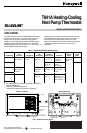
T841A HEATING-COOLING HEAT PUMP THERMOSTAT
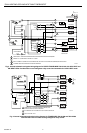
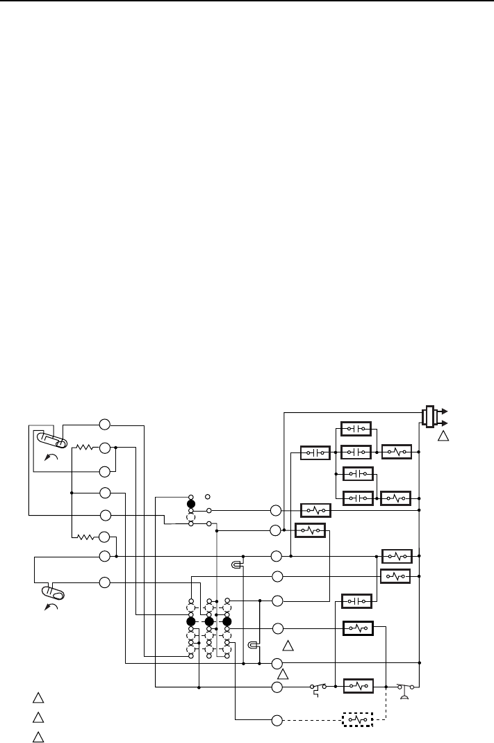
ODT 1
EHR 1
RTD 2
RTD 1
ODT 2
RTD 3
ERH 2
RD
G
SYSTEM
SWITCH
EM. HEAT
HEAT
OFF
COOL
H2
FALL
H1
C1
FALL
H1 & C1
ANTICIPATOR
H2 ANTICIPATOR
FAN
SWITCH
AUTO
ON
COMPRESSOR
CONTACTOR
EM. HEAT
RELAY
CHANGEOVER
RELAY (HEAT)
AUX. HT.
LED (GREEN)
X
W2
B
R
O
LACO
CHP
M1099B
3
CHANGEOVER
RELAY (COOL)
L1
(HOT)
L2
1
L
FAN RELAY
SYSTEM
MONITOR
RTD 1
E
Y
POWER SUPPLY. PROVIDE DISCONNECT MEANS AND OVERLOAD
PROTECTION AS REQUIRED.
WHEN SYSTEM MONITOR IS CONNECTED TO L TERMINAL, EM. HT.
LED ALSO INDICATES COMPRESSOR MALFUNCTION.
X TERMINAL MUST BE CONNECTED FOR PROPER OPERATION.
1
2
3
EM. HT.
LED
(RED)
2
Grasp the thermostat cover at the top and bottom with one
hand. Pull outward on the bottom edge of the cover until it
snaps free of the thermostat base. Carefully remove and
save the packing material surrounding the mercury
switches.
1. Run the wiring (if necessary) to the location. If the
wiring is plastered into the wall, make a hole next to
the cable and loosen the wires so that they can be
pushed back into the wall later. Thread the wires
through the hole in the packing material saved
above. Connect the wires to the terminals on the
back of the thermostat. See Fig. 2 through 5.
2. Set the second stage adjustable heat anticipator to
match the current draw of the primary heating
control (see Heat Anticipator Setting section).
3. Push the excess wire back through the hole and
plug any opening with packing material to prevent
drafts that may affect thermostat performance.
4. Use screws to loosely secure the thermostat to the
wall or outlet box through the two mounting holes in
the middle of the device.
The sheetmetal screws included with the thermostat are
designed for use in plaster walls that do not need anchors.
IMPORTANT
An incorrectly leveled thermostat causes
inaccurate temperature control.
5. Level the thermostat using a spirit level or plumb
line. Tighten the two mounting screws at the middle
of the device.
6. Install the two screws in the top mounting holes and
tighten.
7. Replace the thermostat cover.
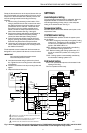
SETTINGS
Heat Anticipator Setting
The second stage heat anticipator is adjustable. Move the
adjustable indicator to match the current draw of the
second stage heating primary control, or the anticipator
setting of the old thermostat. See Fig. 6.
Temperature Setting
Move the setpoint lever to the desired control point on the
temperature scale.
SYSTEM Switch Setting
The SYSTEM switch positions control the system opera-
tion as follows:
EM. HEAT: Emergency heat relay is energized. Cooling
system is off. Compressor is de-energized. Fan runs
on call for heat if FAN switch is in the AUTO
position. EM. HEAT LED is on.
HEAT: Heating system is automatically controlled by
the thermostat. Cooling system is off.
OFF: Both the heating and cooling systems are off. If
the fan is at the AUTO position, the cooling fan is
also off.
COOL: Cooling system is automatically controlled by
the thermostat. Heating system is off.
FAN Switch Setting
AUTO: Fan operates in response to thermostat in both
heating and cooling.
ON: Fan operates continuously.
Fig. 2. Internal schematic and typical wiring diagram for TRADELINE® T841A1308 with EM. HEAT and AUX. HEAT
LEDs. No fan control in EM. HEAT. Provides heat or cool changeover relay control.