


69-0452—8
2
T841A HEATING-COOLING HEAT PUMP THERMOSTAT
OPERATION
The stages of heat
make
sequentially as the temperature
drops.
Make
refers to the mercury switch initiating a call for
heat or cool.
There is about 1°F (0.6°C) between stages so the second
stage (auxiliary heat) makes only when the first stage
cannot handle the load. This 1°F is the
interstage differen-
tial
.
The LED indicators on certain thermostat models light up
when something specific happens within the system.
When the green or amber LED lights, the auxiliary heat
(second stage heat) is operating because the weather is
so cold, the heat pump alone cannot handle the load.
When the red EM. HEAT LED lights, the emergency heat
is operating (usually electric strip heaters), because the
homeowner has physically switched to the EM. HEAT
position. See heating/cooling manufacturer instructions for
specific meaning.
RECYCLING NOTICE
This control contains mercury in a sealed tube. Do
not
place the control in the trash at the end of its
useful life. If this control is replacing a control that
contains mercury in a sealed tube, do
not
place
your old control in the trash.
Contact your local waste management authority for
instructions regarding recycling and the proper
disposal of this control, or any control containing
mercury in a sealed tube.
INSTALLATION
When Installing this Product…
1. Read these instructions carefully. Failure to follow
them could damage the product or cause a hazard-
ous condition.
2. Check the ratings given in the instructions and on
the product to make sure the product is suitable for
your application.
3. Installer must be a trained, experienced technician.
4. After installation is complete, check out product
operation as provided in these instructions.
CAUTION
1. Disconnect power supply to prevent electrical
shock or equipment damage.
2. To prevent interference with the thermostat
linkage, keep wire length to a minimum and
run wires as close as possible to the thermo-
stat base.
3. Do not overtighten the thermostat captive
mounting screws, because damage to the
threads can result.
4. Do not short across coil terminals on the relay.
This can burn out the thermostat heat
anticipator.
5. Never install more than one wire per terminal
unless a factory-supplied jumper with spade
terminal is used.
Location
Locate the thermostat about 5 ft (1.5m) above the floor in
an area with good air circulation at average room tempera-
ture.
Do not mount the thermostat where it can be affected by:
— drafts, or dead spots behind doors and in corners.
— hot or cold air from ducts.
— radiant heat from sun, appliances or fireplaces.
— concealed pipes and chimneys.
— unheated (uncooled) areas such as an outside wall
behind the thermostat.
This thermostat is a precision instrument and was carefully
adjusted at the factory.
Handle it carefully.
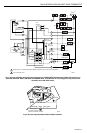
Mounting and Wiring
CAUTION
Disconnect power supply before beginning
installation. Can cause electrical shock or
equipment damage.
The T841A can be mounted directly to a wall or
horizontal outlet box. Choose the method that best fits
your installation.
In replacement applications, check the existing thermostat
wires for cracked or frayed insulation. Replace wires in
poor condition.
All wiring must comply with local codes and ordinances.