


2
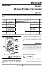
LOCATION
Locate the thermostat about 5 ft. [1.5 m] above the floor
on an inside wall in an area with good air circulation at
average temperature.
Do not mount the thermostat where it can be affected by:
— drafts or dead spots behind doors or in corners.
— hot or cold air from ducts.
— radiant heat from the sun, fireplaces, or appliances.
— unheated (uncooled) areas behind the thermostat, such
as outside walls.
This thermostat is a precision instrument and was care-
fully adjusted at the factory. Handle it carefully.
MOUNTING AND WIRING
Disconnect power supply before beginning installation to
prevent electrical shock or equipment damage.
All wiring must comply with local codes and ordinances.
The T834C can be mounted directly to a wall or vertical
outlet box. Use Honeywell part no. 193121A (beige) or
202689A (gray) Mounting Plate Assembly (order sepa-
rately) to mount on horizontal outlet box or cover marks left
by old thermostat. If mounting plate assembly is used, review
instructions provided with assembly before wiring and mount-
ing thermostat. To wire and mount thermostat:
1. In replacement applications, check the existing ther-
mostat wires for cracked or frayed insulation. Replace any
wires in poor condition. If the wire is plastered into the wall,
make a hole next to the wires and loosen the wires so that they
can be pushed back into the wall later.
2. In new installations, run wiring (if necessary) to the
thermostat location.
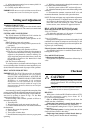
3. Set the adjustable heat anticipator indicator to match
the current draw of the primary heating control or as recom-
mended by the equipment manufacturer (see Heat Anticipa-
tor Setting).
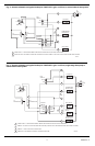
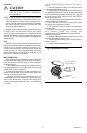
4. Connect the wires to the terminals on the back of the
thermostat. See Figs. 3-5 for internal schematic and typical
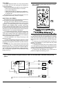
hookup diagrams. If using electric heat-compatible thermo-
stat in central electric heat applications, jumper terminals 1
and 2 to control fan operation from the thermostat during
heating. See Fig. 2.
Fig. 2—Jumpering thermostat terminals to control
fan operation.
5. Remove thermostat cover by pulling outward on bot-
tom edge until it snaps free of the thermostat base. Carefully
remove and discard the foam plastic shipping insert. This
insert protects the switch and bimetal assembly during ship-
ping.
6. Push excess wire back through the hole and plug any
opening with insulation to prevent drafts that may affect
thermostat performance.
7. Fasten the thermostat to the wall or outlet box with a
screw through the top mounting hole. Adjust the thermostat
so that it is approximately level and fasten the second screw
through the bottom mounting hole. Do not tighten.
8. Exactly level the thermostat using a spirit level or
plumb line. Tighten the mounting screws.
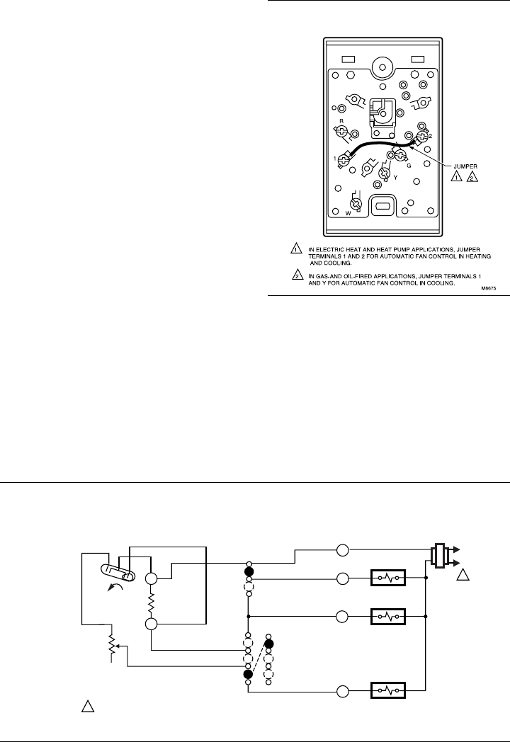
Fig. 3—Internal schematic and typical hookup for T834C1137 and T834C2308 in a standard heating-cooling
system.
H1
TEMP. FALL
C1
L1
(HOT)
L2
1
1
POWER SUPPLY. PROVIDE DISCONNECT MEANS AND OVERLOAD PROTECTION AS REQUIRED.
HEAT RELAY
COMPRESSOR
CONTACTOR
FAN RELAY
FAN SWITCH
ON
AUTO
COOL
OFF
HEAT
COOL
OFF
HEAT
SYSTEM
SWITCH
C1
ANTICIPATOR
H1
ANTICIPATOR
M1119A
W
Y
G
R