


69-0917—2
2
T8112C,D ELECTRONIC PROGRAMMABLE THERMOSTATS
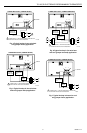
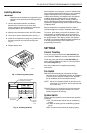
1. Remove mounting plate from the wall, and drill
3/16 inch holes in wall (if drywall) as marked. For
firmer material such as plaster or wood, drill
7/32 inch holes. Gently tap anchors (provided) into
drilled holes until flush with the wall.
2. Reposition mounting plate over holes, pulling
wires through wiring opening. Loosely insert two
mounting screws into holes.
3. Level for appearance only; the thermostat will
function properly even when not level. Tighten
mounting screws. See Fig. 2.
IMPORTANT
When using a high efficiency furnace such as a
90 percent or greater AFUE (Average Fuel
Utilization Efficiency) unit, adjust screw A out
one turn and screw B in.
LEVEL
M1714A
Fig. 2. Leveling mounting plate.
Adjust Fan Operation Switch,
as Required
The Thermostat fan operation switch, labeled FUEL
SWITCH is factory set in the F position. See Fig. 4. This
is the correct setting for most systems. If your system is
an electric heat system, set the switch to E. The E setting
allows the fan to turn on immediately with the heating or
cooling in a system where the G terminal is connected.
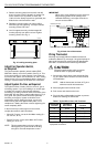
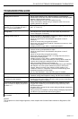
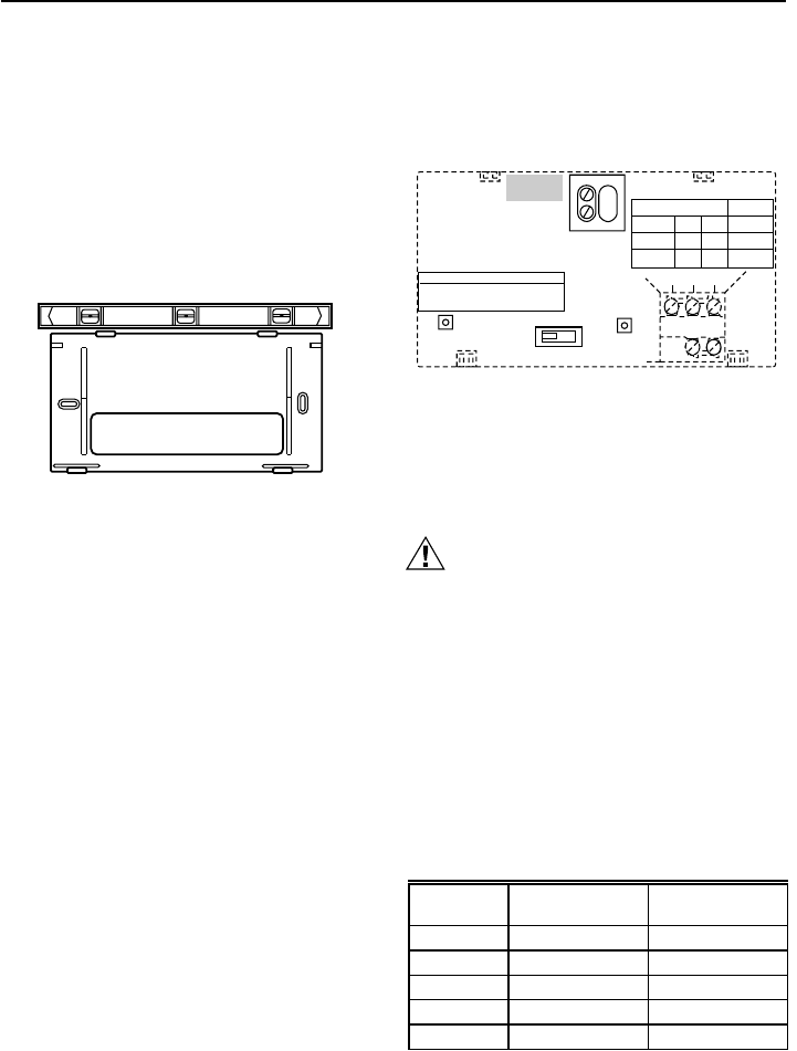
Adjust System On-time, as Required
The system on-time is factory-set for a warm air, gas or
oil heating system. If you are installing it on another type
of system, the system on-time must be adjusted
accordingly by setting screws A and B on the back of the
thermostat. Use the heating system table shown in Fig. 3
as a guide. The system on-time should be optimized
according to the type of system to minimize room
temperature swings. Setting the screw
out one turn
means turning the screw approximately 360° or one
complete turn. Setting the screw
in
means tightening the
screw completely down.
In the event that you want longer furnace on-time,
readjust the screws A and B as follows:
• Warm Air Furnace—set at the Hot Water setting (A—
out one turn, B—in).
• Electric Furnace—Leave at the Warm Air Furnace
setting (A—in, B—in).
NOTE: This thermostat does not have a setting for
steam/gravity air. Cycles would not be long
enough for accurate temperature control.
M3669
R
Rc
W Y G
B D
A C
THERMOSTAT BACK
FOR HIGH EFFICIENCY FURNACE (90%+ AFUE)
SCREW A–OUT 1 TURN
SCREW B–IN
FUEL SWITCH – F POSITION
F
E
FUEL SWITCH
WARM AIR
FURNACE
A–IN
ADJUST SCREWS THROUGH HOLES
TO SELECT OPERATION DESIRED
B–IN
FUEL SWITCH
POSITION
HEATING SYSTEM
ELECTRIC
FURNACE
HOT WATER
BOILER
A–IN
A–OUT
1 TURN
B–IN
B–OUT
1 TURN
E
F
F
ADJUST:
Fig. 3. Back view of thermostat.
Wiring Thermostat
All wiring must comply with local electrical codes and
ordinances. Refer to Fig. 4 through 7 for typical hookups. A
letter code is located near each terminal for identification.
See Table 1 for terminal cross referencing information.
CAUTION
Disconnect power before wiring to prevent
electrical shock or equipment damage.
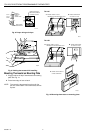
1. Connect the system wires to the thermostat. See
Fig. 8. A letter code is located near each terminal
for identification.
NOTE: Hold the thermostat as shown in Fig. 9 to
minimize need for wire extenders.
2. Securely tighten each terminal screw.
3. Push excess wire back into the hole.
4. Plug hole with nonflammable insulation to prevent
drafts from affecting the thermostat.
Table 1. Typical Wire Colors and Functions
a
Wire colors are typical; verify at heating/cooling
equipment connection.
Thermostat
Terminal
Connect to
Wire Color
a
Function
G Green Fan
Y Yellow Cooling
W White Heating
Rc Blue Air Cond. Power
R Red Furnace Power