


69-1596 G.H. 12-01 www.honeywell.com/yourhome
T8034C HEATING AND COOLING THERMOSTAT
Printed in U.S.A. on recycled
paper containing at least 10%
post-consumer paper fibers.
$XWRPDWLRQDQG&RQWURO6ROXWLRQV $XWRPDWLRQDQG&RQWURO6ROXWLRQV
+RQH\ZHOO +RQH\ZHOO/LPLWHG+RQH\ZHOO/LPLWpH
'RXJODV'ULYH1RUWK '\QDPLF'ULYH
*ROGHQ9DOOH\01 6FDUERURXJK2QWDULR
09=
Heating
With System switch set at Heat, and Fan switch set at
Auto, move the temperature setting lever about 10°F
(6°C) above room temperature:
Gas or oil-fired systems: heating should start; fan
should start after a short delay.
Central electric heat or heat pump systems: both
heating and fan should start.
Move the temperature setting lever about 10°F (6°C)
below room temperature:
Gas or oil-fired systems: heating should shut off and
fan should shut off after a short delay.
Electric heat or heat pump systems: heating and fan
should shut off.
Cooling
CAUTION
Equipment Damage Hazard.
Air conditioning equipment (compressor) can
be damaged.
Do not operate cooling when outdoor
temperature is below 50°F (10°C). Refer to
manufacturer’s recommendations.
IMPORTANT
To prevent compressor short cycling, some
manufacturer’s equipment includes a minimum-
off timer to provide a five-minute time delay
from when the thermostat last turned off the
compressor, or from when the system first
received power. This delay protects the com-
pressor.
WIth the System switch set at Cool and the Fan switch
set to Auto, move the temperature setting lever about
10°F (6°C) below room temperature. Cooling and fan
should start (see Important above). Move the
temperature setting lever about 10°F (6°C) above room
temperature. Cooling and fan should shut off.
Fan
With the System switch set to Off and the Fan switch set
to On, the fan should run continuously. Move the Fan
switch to Auto. In gas- or oil-fired systems, fan operation
is controlled by the plenum fan control in heating and by
the thermostat in cooling. In central electric heat and heat
pump systems, fan operation is controlled by the
thermostat in both heating and cooling.
Recalibration
These thermostats are calibrated at the factory and
should not need recalibration. If the thermostat seems
out of adjustment, first check for accurate leveling.
To check calibration:
1. Move the temperature setting lever to the lower
end of the temperature scale. Place the System
switch to the Off position. Wait at least five min-
utes.
2. Remove the thermostat cover. Move the setting
lever until the switch just makes contact. (The mer-
cury in the switch rolls to the left end of the tube.)
3. Replace the cover and wait five minutes for the
cover and the thermostat to lose the heat it has
gained from your hands. If the thermometer pointer
and the setting lever indicator read approximately
the same, no recalibration is needed.
If recalibration appears necessary:
1. Place the temperature setting lever at the same
setting as the thermometer. Remove the cover by
pulling out on the right edge of the cover until it
snaps free of the thermostat base.
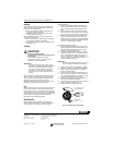
2. Insert the 104994A Calibration Wrench (ordered
separately) onto the hex nut under the coil. (See
Fig. 4.) Holding the setting lever so it does not
move, turn the wrench clockwise until the mercury
rolls to the right end of the tube. Remove the
wrench and replace the cover.
IMPORTANT
To assure accurate temperature control, do not
touch or breathe on bimetal or thermometer.
3. Move the setting lever to a lower setting. Wait at
least five minutes for the temperature to stabilize.
4. Slowly move the setting lever until it reads the
same as the thermometer.
5. Remove the cover. Holding the setting lever so it
does not move, reinsert the wrench and carefully
turn it counterclockwise just until the mercury rolls
to the left end of the tube but no farther.
6. Recheck the calibration. Set the thermostat Sys-
tem switch for the desired operation.
7. Adjust the temperature setting lever so the mercury
bulb is in position as shown in Fig. 4.
8. Carefully replace the thermostat cover.
Fig. 4. Recalibrating the thermostat.
CALIBRATION
WRENCH
COIL SHOWN WITHOUT
HEAT ANTICIPATOR
M2044A