


T8034C HEATING AND COOLING THERMOSTAT
69-1596 2
Location
Locate the thermostat about 5 ft (1.5m) above the floor
on an inside wall in an area with good air circulation at
average temperature.
Do not mount the thermostat where it can be affected by:
— drafts or dead spots behind doors or in corner.
— hot or cold air from ducts.
— radiant heat from the sun, fireplaces or appliances.
— unheated (uncooled) areas such as outside walls
behind the thermostats.
This thermostat is a precision instrument and was
carefully adjusted at the factory. Handle it carefully.
Wiring and Mounting
CAUTION
Electrical Shock Hazard.
Can cause personal electrical shock and
equipment damage.
Disconnect power supply before beginning
installation.
IMPORTANT
All wiring must comply with local codes and
ordinances.
The T8034C can be mounted directly on a wall or
horizontal outlet box:
— Use the 200581 (beige) or 202895A (gray) Horizontal
Wallplate to cover mounting marks from an old
thermostat.
— Use the 19312A (beige) or 202689A (gray) Mounting
Plate Assembly to mount on vertical outlet box or to
cover wall marks where larger plate is needed.
The SUPER TRADELINE® T8034C includes the 200581
Horizontal Wallplate. For other T8043C models, order the
horizontal wallplate or mounting plate assembly.
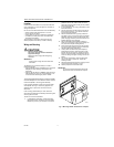
If the horizontal wallplate is used, align the thermostat
and wallplate. See Fig. 2. Press firmly together until
wallplate snaps in place, then wire and mount the
thermostat.
If the mounting plate assembly is used, review the
instructions provided with the assembly before wiring and
mounting the thermostat.
To wire and mount the thermostat:
1. In replacement applications, check the existing
thermostat wires for cracked or frayed insulation.
Replace any wires in poor condition. If the wire is
plastered into the wall, make a hole next to the
wires and loosen the wires so they can be pushed
back into the wall later.
2. In new installations, run wiring (if necessary) to the
thermostat location.
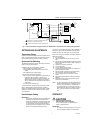
3. Connect the wires to the terminals on the back of
the thermostat. See Fig. 3 for internal schematic
and typical hookup diagram.
4. Remove thermostat cover by pulling outward on
right edge of cover until it snaps free of the thermo-
stat base. Carefully remove and discard the foam
plastic shipping insert that protects the switch and
bimetal assembly during shipping.
5. Set the adjustable heat anticipator indicator to
match the current draw of the primary heating con-
trol (see Heat Anticipator Setting section).
6. Push excess wire back through the hole and plug
any opening with insulation to prevent drafts that
can affect thermostat performance.
7. Loosely fasten the thermostat (with wallplate, if
applicable) to the wall or outlet box with a screw
through the left mounting hole. Adjust the thermo-
stat so it is approximately level and fasten the sec-
ond screw through the right mounting hole. Do not
tighten.
8. For optimum performance, level the thermostat
using a spirit level or plumb line. Tighten the
mounting screws.
9. Adjust temperature setting lever so mercury bulb is
in horizontal position as shown in Fig. 2.
10. Carefully replace the thermostat cover.
IMPORTANT
An incorrectly leveled thermostat causes the
temperature control to deviate from setpoint.
Fig. 2. Mounting T8034C Thermostat on wallplate.
Heat
O
f
f
C
o
o
l
O
n
FAN
Auto
UP
M20287
90
80
70
60