


T775A,B,C,D REMOTE TEMPERATURE CONTROLLER
63-2489—2 10
CHECKOUT
Error Messages
There are seven error messages that can display in response
to T775 software or hardware problems. The error Codes that
can flash on the display are:
• SF: Sensor Failure
— A flashing SF indicates an out-of-range or defective
sensor. Make sure that the sensors are connected
properly. For T775A,C all loads de-energize when this
error message flashes.
— For the T775B,D the loads controlled by the out-of-
range sensor de-energize. The display flashes SF to
indicate which sensor is defective or in error. In the
event that only one sensor is defective, the remaining
sensor and its load(s) operate normally. Only the
load(s) controlled by the defective, out-of-range, or
unconnected sensor de-energize.
NOTE: Sensor values below -40°F or above 220°F are
out-of-range.
• EF: EEPROM Failure
— The values read back from the EEPROM are not the
same as written into the EEPROM. This error cannot
be field repaired. Replace the device. The EEPROM is
not intended to be field repaired.
• CF: Calibration Failure
— A calibration resistor reading was not within the range
of the Analog to Digital converter. This error cannot be
field repaired. Replace the device.
• OF: Stray Interrupt Failure
— An unused interrupt occurred. This error cannot be field
repaired. Replace the device.
• CE: Configuration Error
— The device hardware was configured to a nonexistent
device. This error cannot be field repaired. Replace the
device.
• OE: ROM Error
— The internal Read Only Memory (ROM) of the micro-
processor is defective. This error cannot be field
repaired. Replace the device.
• AE: RAM error
— The internal Random Access Memory (RAM) of the
microprocessor is defective. This error cannot be field
repaired. Replace the device.
Setpoint Calibration
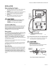
To maintain temperature accuracy, use 18 AWG two-conductor
sensor wires. If the length of the sensor wire exceeds 400 feet,
recalibration will be necessary to maintain accuracy. Table 4
shows the corresponding temperature offset to use for different
sensor wire lengths. This temperature offset should be added
to the desired temperature setpoint for these applications.
Refer to programming instructions in the Programming section
for entering temperature setpoints.
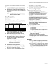
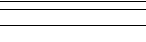
Table 4. Temperature Offset Based on Wire Length.
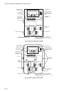
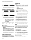
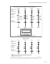
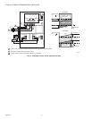
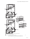
After the controller is installed and wired, apply power. Make
initial adjustments and desired settings:
1. As shown in Fig. 10, record the sensed temperatures for
both Sensor A and Sensor B as displayed on the device.
Use the Select key to advance through the programming
loop to determine and then write, on the Checkout Table
(Fig. 10), the loads controlled by each sensor.
2. Write the operating mode (heat or cool) for each stage in
the Checkout Table (Fig. 10).
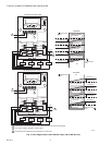
3. Write the sensed temperature for each load on the
Sensed Temp line.
4. Write the differential for each load on the Differential line.
5. Write the setpoint for each stage (Off temperature). Cal-
culate the “On Temperature” for each stage.
NOTE: “On temperature” is setpoint plus differential for
cooling, and it is setpoint minus differential for
heating.
6. Plot the on and off (open/closed) values at which the
device will energize and de-energize each output load,
(Refer to the Device Programming Worksheet.)
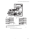
7. Verify which loads are energized by using the Checkout
Table (Fig. 10). As shown in the example, the display
indicates, in the lower right corner, energized stages. If
no stages are energized, the words “stage energized”
will not appear.
NOTE: If the sensed temperature is between the On
and Off temperatures, the load may either be
energized or de-energized. Refer to the Control
Algorithm section (in Operation) for further
explanation.
8. If an error message flashes, refer to the description of
these messages. If SF flashes:
a. Check sensor connections.
b. If properly connected and SF continues to flash,
check the sensor location to make sure it is located
in an ambient condition that is within the sensor
capability (-40° to +220°F).
9. If an error message other than SF flashes, the device
cannot be field repaired. Replace the device.
Sensor Wire Length Calibration Offset
0 to 399 ft None required.
400 to 599 ft 1.0 degrees
600 to 799 ft 2.0 degrees
800 to 1000 ft 3.0 degrees