


T7351 COMMERCIAL PROGRAMMABLE THERMOSTAT
11 62-0258
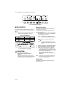
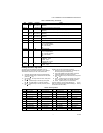
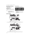
Fig. 9. Typical hookup of T7350F2010 in three-stage heat and three-stage cool conventional system
with one transformer.
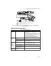
TROUBLESHOOTING GUIDE (TABLE 7)
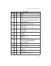
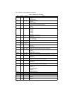
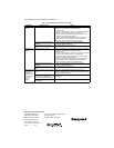
Table 7. Troubleshooting Information.
Symptom Possible Cause Action
Display will not
come on.
Thermostat is not being powered. Check that X terminal is connected to the system transformer.
Check for 24 Vac between X and RH terminals.
If missing 24 Vac:
• Check if circuit breaker is tripped; if so, reset circuit breaker.
• Check if system fuse is blown; if so, replace fuse.
• Check if the HVAC equipment power switch is in the Off
position; if so, set to the On position.
• Check wiring between thermostat and HVAC equipment.
Replace broken wires and tighten loose connections.
If 24 Vac is present, proceed with troubleshooting.
Temperature
display is
incorrect.
Thermostat is configured for °F or
°C display.
Press both Run Schedule and Copy, then reconfigure the
display.
Bad thermostat location. Relocate the thermostat.
Display shows three dashes and a
degree sign (all systems shut
down).
T7351 is set for remote sensing and sensor is missing or circuit
is either open or shorted.
Temperature
settings will not
change.
(Example:
Cannot set
heating higher or
cooling lower.)
Upper or lower temperature limits
were reached.
Check the temperature setpoints:
• Heating limits are 40 to 90°F (7 to 31°C)
• Cooling limits are 45 to 99°F (9 to 37°C)
Occupied setpoint temperature
range stops were configured.
Check setpoint stops. If necessary, reconfigure the stop(s).
Keypad is locked. When a locked
key is pressed, LOCKED appears
momentarily on the LCD.
Press both Run Schedule and Copy, then change keypad lock
level.
Room
temperature is
out of control.
Remote temperature sensing is not
working.
Check all remote sensors.
POWER SUPPLY. PROVIDE DISCONNECT MEANS AND OVERLOAD PROTECTION AS REQUIRED.
ENSURE TRANSFORMER IS SIZED TO HANDLE THE LOAD.
HEAT/COOL SYSTEMS WITH ONE TRANSFORMER REQUIRE THE FACTORY-INSTALLED JUMPER.
USE ECONOMIZER INSTRUCTIONS FOR INSTALLATION DIRECTIONS.
1
M25319
2
3
2
3
4
RC
AUX
X
SUBBASE
W1 G
T7770 REMOTE SENSOR
Y1
W3/Y4 Y3 W2 Y2
AUXRH
T5 T6 T7 T4 T3
DISCHARGE
AIR
SENSOR
OUTDOOR
AIR
SENSOR
MOTION
SENSOR
HUMIDITY
SENSOR
M
OSOS ASAS
MHC HPHS
1
4
L1
(HOT)
L2
COMPRESSOR
CONTACTOR 1
COMPRESSOR
CONTACTOR 2
HEAT
RELAY 1
123456789
FAN
RELAY
ECONOMIZER
HEAT
RELAY 2
COMPRESSOR
CONTACTOR 3
HEAT
RELAY 3