


T7351 COMMERCIAL PROGRAMMABLE THERMOSTAT
62-0258 10
Options Utilizing Auxiliary Output
There are two dehumidification options that utilize the
auxiliary output. They are:
— Simple Dehumidification.
— Hot Gas Bypass Dehumidification.
Simple Dehumid(ification)
The auxiliary output:
— Energizes when RH rises above humidity high limit.
— De-energizes when RH drops below humidity high
limit.
NOTES:
— Hysteresis and a minimum timer prevent
short cycling of this output.
— Unlike Dehumid Hot Gas BP the relay
remains energized during calls for multiple
cooling stages.
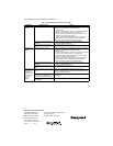
Dehumid Hot Gas BP
The auxiliary output operates as shown in Table 6.
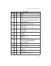
Table 6. Hot Gas Bypass Dehumidification Logic.
Auxiliary output during call for multiple cooling stages for
two reasons:
1. This method assumes that the cooling provides
dehumidification.
2. Multiple cooling stages probably provide necessary
dehumidification.
3. Hysteresis and a minimum timer prevent short
cycling of this output.
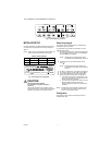
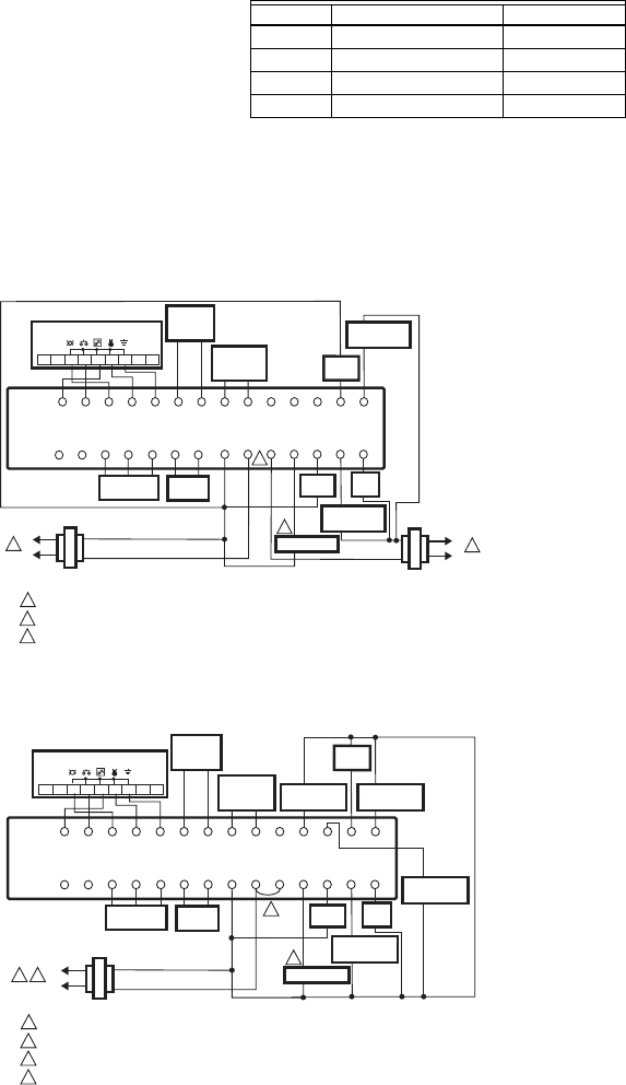
WIRING DIAGRAMS
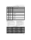
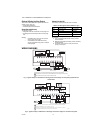
Fig. 7. Typical hookup of T7351F2010 in two-stage heat and two-stage cool heat pump system with two
transformers.
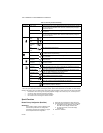
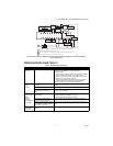
Fig. 8. Typical hookup of T7351F201U in two-stage heat and four-stage cool conventional system.
Humidity Cooling Stages Active Auxiliary Output
High more than one De-energized
High one or less Energized
Low more than one De-energized
Low one or less De-energized
POWER SUPPLY. PROVIDE DISCONNECT MEANS AND OVERLOAD PROTECTION AS REQUIRED.
WHEN INSTALLED ON A SYSTEM WITH TWO TRANSFORMERS, REMOVE THE FACTORY-INSTALLED JUMPER.
USE ECONOMIZER INSTRUCTIONS FOR INSTALLATION DIRECTIONS.
1
M25324
2
2
3
RCX
SUBBASE
W1 G
T7770 REMOTE SENSOR
Y1
W2 Y2
AUX
RH
T5 T6 T7 T4 T3
DISCHARGE
AIR
SENSOR
OUTDOOR
AIR
SENSOR
OSOS ASAS
1
3
L1
(HOT)
L2
1
L1
(HOT)
L2
COMPRESSOR
CONTACTOR 1
COMPRESSOR
CONTACTOR 2
HEATING
TRANSFORMER
COOLING
TRANSFORMER
HEAT
RELAY 1
123456789
FAN
RELAY
ECONOMIZER
HEAT
RELAY 2
MOTION
SENSOR
HUMIDITY
SENSOR
MMHC HPHS
POWER SUPPLY. PROVIDE DISCONNECT MEANS AND OVERLOAD PROTECTION AS REQUIRED.
ENSURE TRANSFORMER IS SIZED TO HANDLE THE LOAD.
HEAT/COOL SYSTEMS WITH ONE TRANSFORMER REQUIRE THE FACTORY-INSTALLED JUMPER.
USE ECONOMIZER INSTRUCTIONS FOR INSTALLATION DIRECTIONS.
1
M19768A
2
3
2
3
4
RCX
SUBBASE
W1 G
T7770 REMOTE SENSOR
Y1
W3/Y4 Y3 W2
Y2
AUXRH
T5 T6 T7 T4
T3
DISCHARGE
AIR
SENSOR
OUTDOOR
AIR
SENSOR
MOTION
SENSOR
HUMIDITY
SENSOR
M
OSOS ASAS
MHC HP
HS
1
4
L1
(HOT)
L2
COMPRESSOR
CONTACTOR 1
COMPRESSOR
CONTACTOR 2
HEAT
RELAY 1
123456789
FAN
RELAY
ECONOMIZER
HEAT
RELAY 2
COMPRESSOR
CONTACTOR 3
COMPRESSOR
CONTACTOR 4