


5 63-2051—4
T451A, T651A, T694A,B,D,F
INSTALLATION
1. Before mounting thermostat, connect system wiring
to proper terminals at rear of thermostat. Follow equip-
ment manufacturer instructions or refer to Fig. 4 for
typical system hookup.
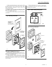
2. Remove cover assembly from thermostat. Attach
thermostat to junction box with two screws provided. Re-
place cover assembly. See Fig. 3.
3. Use 1/16 hex Allen wrench to install Allen locking
cover screw.
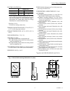
Fig. 3—Mounting T451A/T651A.
F
40 50 60 70 80 90
M6131
50
60
70
80
90
40
USE 2x4
JUNCTION
BOX
MOUNTING
SCREWS (2)
TABS HOLD
COVER ASSEMBLY
AT TOP (SNAP
IN AT BOTTOM)
220213 WALLPLATE
ACCESSORY
(OPTIONAL)
(COVERS OLD T651A
WALL MARKS WHEN
INSTALLING NEW T651A)
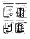
T694A,B,D,F THERMOSTATS (Fig. 5)
All T694A,B,D,F Thermostats mount vertically on a 2 x
4 in. or 4 x 4 in. junction box. See Fig. 5. Use 2 x 4 in. cover
plate with 4 x 4 in. junction box.
1. Before mounting, connect system wiring to proper
color-coded leads at rear of thermostat. Follow equipment
manufacturer instructions or refer to Figs. 6-9 for typical
system hookups.
2. Remove thermostat cover assembly. Attach thermo-
stat to junction box with two screws provided. Replace
thermostat cover assembly.
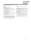
Fig. 4—T652A in heating-cooling system.
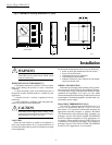
Fig. 5—Mounting T694A,B,D,F.
F
40
50
60
70
80
90
SYSTEM
ON
OFF
HEAT
COOL
FAN
HI
MED
LOW
M6135
COVER PLATE
4x4 JUNCTION
BOX
USE 2x4 OR 4x4
JUNCTION BOX
(T694B SHOWN)
MOUNTING
SCREWS (2)
TABS HOLD
COVER ASSEMBLY
AT TOP (SNAP
IN AT BOTTOM)