


4
T451A, T651A, T694A,B,D,F
INSTALLATION
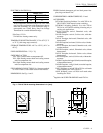
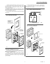
Fig. 2—T694A,B,D,F mounting dimensions in in. [mm].
1
13
32
[
36
]
15
32
[35]
4
7
8
[124]
4
29
32
[125 ]
40
50
60
70
80
90
3
9
32
[83]
1
9
16
[40]
3
[76]
1
7
8
[48]
SYSTEM
ON
OFF
HEAT
COOL
FAN
HI
MED
LOW
F
M6129
(T694B SHOWN)
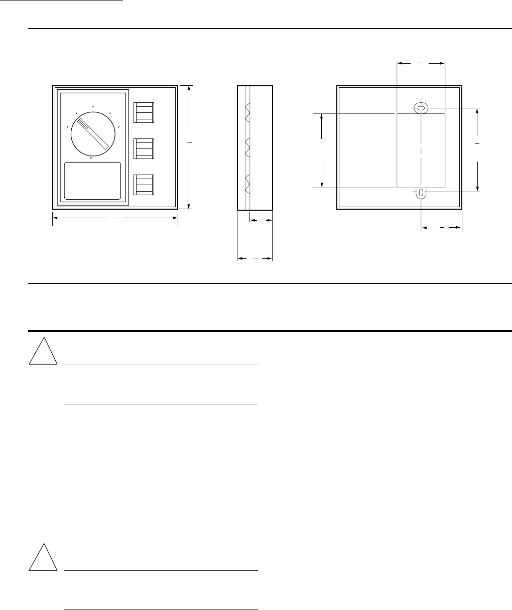
Installation
!
WARNING
Do not use on electric heat. Possible fire hazard if
T694A,B,D used on electric heat. T694F can be
used on electric heat.
WHEN INSTALLING THIS PRODUCT…
1. Read these instructions carefully. Failure to follow
them could damage the product or cause a hazardous
condition.
2. Check the ratings given in the instructions and on
the product to make sure the product is suitable for your
application.
3. Installer must be a trained, experienced service
technician.
4. After installation is complete, check out product op-
eration as provided in these instructions.
CAUTION
Disconnect power supply before making wiring
connections to prevent electrical shock and equip-
ment damage. Use copper wire only.
LOCATION
Select the same location as control to be replaced, or
select a new location about 5 ft. [1.5 m] above the floor, on
an inside wall where there is good air circulation at average
room temperature.
Do not install the thermostat where it may be affected by:
•drafts, or dead spots behind doors and in corners.
• hot or cold air from ducts.
•radiant heat from sun or appliances.
• concealed pipes and chimneys.
• unheated (uncooled) areas behind the thermostat,
such as an outside wall.
WIRING AND MOUNTING
Disconnect power supply before making wiring connec-
tions to prevent electrical shock and equipment damage.
All wiring must comply with applicable electrical codes,
ordinances and regulations. Use copper wire only. Make
sure that thermostat electrical rating is sufficient for current
requirements of controlled equipment, and that listed volt-
age matches power supply.
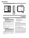
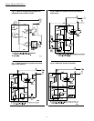
T451A/T651A THERMOSTATS (Fig. 3)
T451A/T651A Thermostats mount vertically on a 2 x 4
in. or 4 x 4 in. junction box. See Fig. 3. Use 2 x 4 in. cover
plate with 4 x 4 in. junction. For horizontal mounting, the
appropriate horizontal faceplate is required. Horizontal
with thermometer and horizontal blank faceplates are
packaged with the T651A2028 SUPER TRADELINE
model. For additional faceplates or T451 applications, see
Accessories. When replacing old style T451A/T651A, use
a wallplate to cover previous wall marks. This wallplate is
packaged with the T651A2028 SUPER TRADELINE
model. For T451 applications, see Accessories.
!