


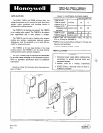
LOCATION
Locate the thermostat about five feet above the floor
on an inside wall where it will be affected only by the
average temperature of the room. These thermostats are
:mounted vertically.
If using a Q651 Subbase, refer to the instructions
packed with the subbase.
MOUNTING
1. Mount a 2,by 4 inch outlet box either vertically
or horizontally depending on the model used. Models
with vertical faceplate mount on vertical outlet box;
models with horizontal faceplate mount on horizontal
outlet box.
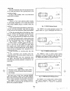
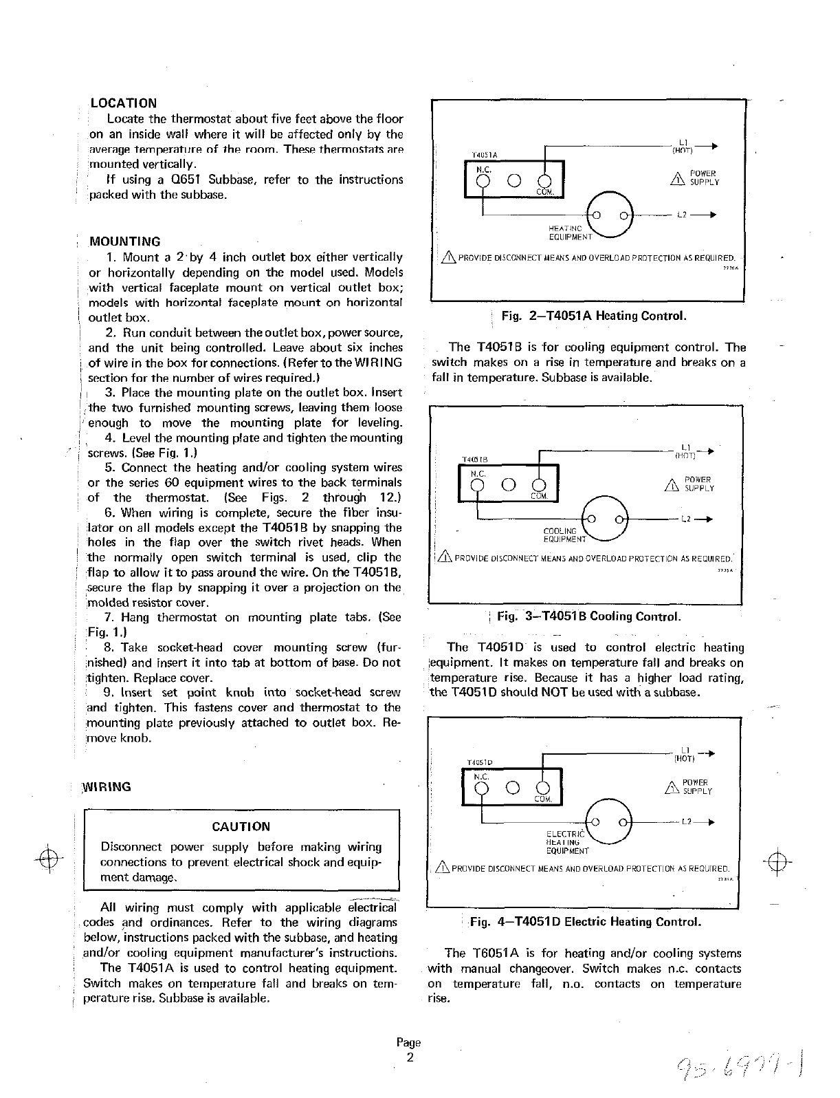
Fig. Z-T4051A Heating Control.
2. Run conduit between the outlet box, powersource,
and the unit being controlled. Leave about six inches
The T40516 is for cooling equipment control. The
of wire in the box forconnections. (Refertothe WIRING
switch makes on a rise in temperature and breaks on a
section for the number of wires required.)
fall in temperature. Subbase is available.
3. Place the mounting plate on the outlet box. Insert
the two furnished mounting screws, leaving theme loose
enough to move the mounting plate for leveling.
4. Level the mounting plate and tighten the mounting
screws. (See Fig. 1.)
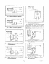
5. Connect the heating and/or cooling system wires
or the series 60 equipment wires to the back terminals
of the thermostat. (See Figs. 2 through 12.)
6. When wiring is complete, secure the fiber insu-
lator on all models except the T4051 B by snapping the
holes in the flap over the switch rivet heads. When
the normally open switch terminal is used, clip the
flap to allow it to pass around the wire. On the T4051 B,
secure the flap by snapping it over a projection on the,
molded resistor cover.
7. Hang thermostat on mounting plate tabs. (See
Fig. 3-T4051 B Cooling Control.
Fig. 1.)
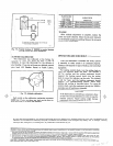
8. Take socket-head cover mounting screw (fur- The T4051D~ is used to control electric heating
nished) and insert it into tab at bottom of base. Do not equipment. It makes on temperature fall and breaks on
tighten. Replace cover. temperature rise. Because it has a higher load rating,
9. Insert set point knob into socket-head screw the T4051 D should NOT be used with a subbase.
and tighten. This fastens cover and thermostat to the
mounting plate previously attached to outlet box. Re-
move knob.
WIRING
CAUTION
Disconnect power supply before making wiring
connections to prevent electrical shock and equip-
ment damage.
All wiring must comply with applicable electrical
codes and ordinances. Refer to the wiring diagrams
Fig. 4-T4051 D Electric Heating Control.
below, instructions packed with the subbase, and heating
and/or cooling equipment manufacturer’s instructioiw.
The T6051A is for heating and/or cooling systems
The T4051A is used to control heating equipment. with manual changeover. Switch makes n.c. contacts
Switch makes on temperature fall and breaks on tem- on temperature fall, n.0. Contacts on temperature
perature rise. Subbase is available. rise.