


3 62-3047
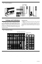
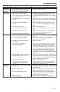
Fig. 4—Typical installations.
M9734
18 INCH
MINIMUM
Settings and Calibration
The T104F Control includes an adjustable range limit-
ing pin (order additional pins separately). The pin is fac-
tory-set to limit the low range of the control to the frost
protection (*) setting (see Fig. 5). The pin can be moved to
a different low or high limit setting and lock point, or it can
be removed. Use a second pin if both low and high limit
settings are desired.
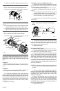
Setting the Limit
To set a limit different from the factory setting, proceed
as follows:
1. Determine the desired temperature range limit or lock-
ing temperature. Select the appropriate number on the ad-
justment knob to match the desired temperature setting. See
Fig. 5.
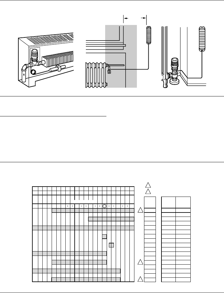
Fig. 5—Temperature settings.
M9729
SCALE MARKING
ADJUSTMENT RANGE SETTING
OFF
OFF
PIN
POS.
TEMP.
RANGE
°F
TEMP.
RANGE
°C
6
01
1PIN REQUIRED.
FACTORY SETTING.
*
*
23
4
56
43
8
46
12
54
16
61
20
68
23
73
26
79
6 - 26
16 - 26
OFF - 26
20
22
0 - 20
6 - 20
0 - 23
6 - 23
43 - 79
61 - 79
OFF - 79
68
72
0 - 68
43 - 68
0 - 73
43 - 73
3
NONE
4a
4b
4b
4b + *
5 + *
5
°C
°F
2
2
1
1