


62-3047 2
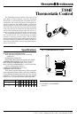
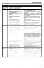
Fig. 2—V110 Valve Bodies.
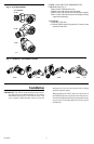
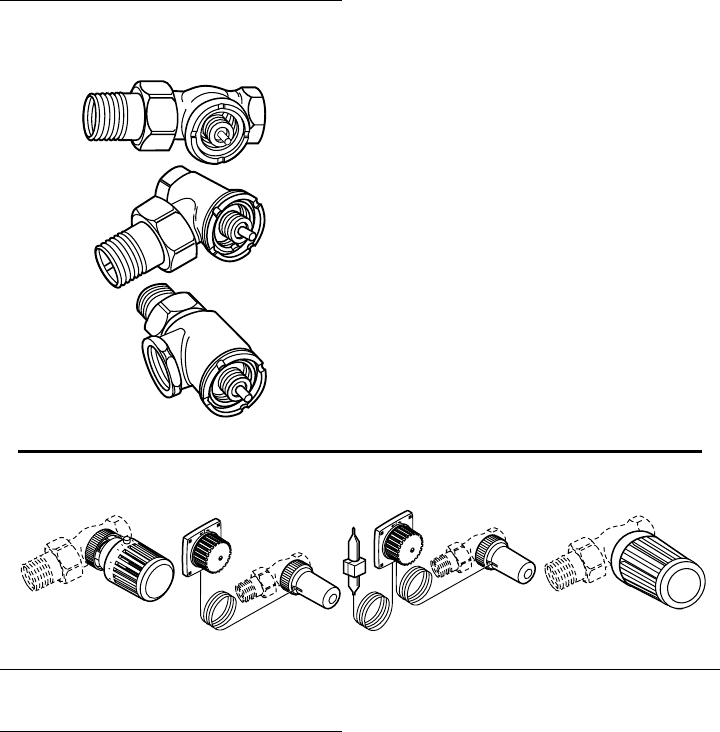
OTHER AVAILABLE T100 THERMOSTATIC
CONTROLS (See Fig. 3):
T104A Control with internal sensor.
T104B Control with remote sensor/setpoint.
T104C Control with remote sensor and remote setpoint.
T104V Control with internal sensor and tamper-resistant
setpoint and mounting.
ACCESSORY
A104F1007 Limit Pins.
G111B1053 Bulb guard for protection of sensor when
mounted on the wall.
M9735
V110D
VALVE BODIES
V110E
V110F
Fig. 3—T104A,B,C,V Thermostatic Controls.
T104B T104CT104A T104V
M9736
1
2
3
4
5
1
2
3
4
5
2
3
Installation
IMPORTANT: The T104F can be mounted inside an enclo-
sure if the sensor is located a minimum of 3 in. (76 mm)
beneath the heating coils in the cold air return. Coil
excess capillary tubing beneath and away from the
heating coils. Take care not to break, kink or sharply
bend the capillary tubing.
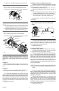
When mounting the T104F, make sure the bosses on
the T104F base fit securely into the valve body grooves.
Firmly hand tighten the knurled ring. Improper mount-
ing can cause overheating. Refer to Fig. 4 for typical
installations.