


7Part Number 550-110-739/0703
GSA
Gas-Fired Steam Boilers – User’s Information Manual
❏ Check monthly
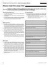
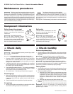
Boiler relief valve
1. After following the warning directions
below, if the relief valve weeps or will
not seat properly, replace the relief valve.
Before testing, make certain
discharge pipe is properly
connected to valve outlet and arranged to
contain and safely dispose of boiler
discharge. Wear gloves to protect your
hands from hot surfaces. Verify that
discharge piping is installed in accordance with this manual and
the instructions on the relief valve tag. Failure to comply will expose
operator and others to severe personal injury or death.
Safety relief valves should be reinspected AT LEAST
ONCE EVERY THREE YEARS, by a licensed
plumbing contractor or authorized inspection agency, to ensure that
the product has not been affected by corrosive water conditions
and to ensure that the valve and discharge line have not been altered
or tampered with illegally. Certain naturally occurring conditions may
corrode the valve or its components over time, rendering the valve
inoperative. Such conditions are not detectable unless the valve
and its components are physically removed and inspected. This
inspection must only be conducted by a plumbing contractor or
authorized inspection agency — not by the owner. Failure to
reinspect the boiler relief valve as directed could result in unsafe
pressure buildup, which can result in severe personal injury, death
or substantial property damage.
Check the setting of the boiler limit control. The
control should never be set with a pressure above
10 psig. Operating at a higher pressure can cause damage to the
boiler relief valve.
The boiler relief valve must be tested at least
monthly during the heating season to verify the valve
and discharge piping flow freely. If corrosion and/or deposits are
noticed within the valve body, testing must be performed more often.
A “try lever test” must also be performed at the end of any non-
service period. Follow the instructions below for a “try lever test”.
• With the system at operating pressure, lift and hold the test
lever fully open for at least 5 seconds to flush the valve seat
free of sediment and debris. Then release lever and permit the
valve to snap shut.
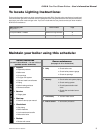
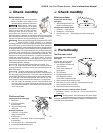
Pilot burner flame
Proper pilot flame (see right):
1. Blue flame.
2. Inner cone engulfing
thermocouple.
3. Thermocouple glowing
cherry red.
Improper pilot flame:
1. Overfired — Large flame
lifting or blowing past
thermocouple.
2. Underfired — Small flame. Inner cone not engulfing
thermocouple.
3. Lack of primary air — Yellow flame tip.
4. Incorrectly heated thermocouple.
Main burner flame
Proper main burner flame
(see right):
1. Yellow-orange streaks may
appear (caused by dust).
Improper main burner flame:
1. Overfired — Large flames.
2. Underfired — Small flames.
3. Lack of primary air — Yellow tipping on flames (sooting will
occur).
❏ Check monthly
❏ Periodically
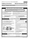
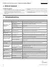
Test low water cutoff
Probe-type low water cutoff
(see right)
Check probe-type low water
cutoff for proper operation.
1. Turn off power to boiler and
wait 5 minutes.
2. Drain water to bottom of
gauge glass.
3. Turn on power.
4. Set thermostat to call for
heat. Red neon lamp on
lower water cutoff should light.
5. Wait 5 minutes. Boiler should not fire.
6. Refill boiler to correct water line. Red lamp should go off.
7. Wait 5 minutes. Boiler should fire.
8. Return thermostat to normal setting.
Float-type low water cutoff (by others, if used)
1. Blowdown control and test per control manufacturer’s
instructions.
Scald potential. Do not blowdown low water cutoff
unless blowdown piping has been installed according
to control manufacturer’s instructions. If piping is not installed, call
a qualified service technician.