


R7824, R7847, R7848, R7849,R7851,R7861, R7886 AMPLIFIERS FOR 7800 SERIES RELAY MODULES
65-0109—8 4
CAUTION
Equipment Damage Hazard.
Incorrect combination of relay module, amplifier
and flame detector can cause equipment damage.
In infrared applications (C7015 Infrared Flame
Detector and R7848 Amplifier) using the RM7890
Relay Module with software version 4004 or less
requires a ten-second delay to start sequence. This
applies only to the initial power of the RM7890.
INSTALLATION
When Installing this Product...
1.
Read these instructions carefully. Failure to follow them
could damage the product or cause a hazardous
condition.
2.
Check the ratings given in the instructions and on the
product to make sure the product is suitable for your
application.
3. Installer must be a trained, experienced, flame
safeguard control technician.
4.
After installation is complete, check out the product
operation as provided in these instructions.
WARNING
Electric Shock Hazard.
Can cause electrical shock, serious injury or
death.
Disconnect the power supply before beginning
installation. More than one power supply
disconnection can be involved.
IMPORTANT
1. Wiring must comply with all applicable codes,
ordinances and regulations
2. Wiring (where required) must comply with NEC
Class 1 (Line Voltage) wiring.
3. Perform all required checkout tests after installation
is complete.
CAUTION
Equipment Damage Hazard.
Can cause equipment damage.
Disconnect 7800 SERIES Relay Module power before
removing amplifier.
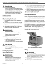
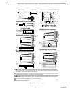
Installing Plug-In Flame
Signal Amplifier (Fig. 2)
WARNING
Electric Shock Hazard.
Can cause electrical shock, serious injury or
death.
Disconnect the power supply before beginning
installation. More than one power supply
disconnection can be involved.
1. Align the amplifier circuit board edge connector with the
keyed receptacle on the 7800 SERIES Relay Module.
Be sure the amplifier nameplate faces away from the
Relay Module.
2.
Push in the amplifier until the circuit board is fully
inserted into the receptacle and then push the amplifier
toward the 7800 SERIES Relay Module retaining clasp.
3.
Be sure the amplifier is firmly in place.
4. Perform all required checkout tests.
Installing Flame Detector
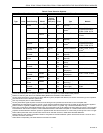
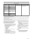
NOTE: NOTE:Table 2 lists flame detection systems available
for use with 7800 SERIES Relay Modules. Be sure to
use the correct combination of amplifier and flame
detector.
Proper flame detector installation is the basis of a safe and
reliable flame safeguard installation. Refer to the Instructions
packed with the flame detector and the equipment manufac-
turer instructions.
Keep the flame signal leadwires as short as possible from the
flame detector to the wiring subbase. Capacitance increases
with leadwire length, reducing the signal strength. The
maximum permissible leadwire length depends on the type of
flame detector, leadwire and conduit. However, the ultimate
limiting factor for the flame detector leadwire is the flame
signal; see Table 3 in the Checkout section.
Fig. 2. Installing flame signal amplifier.
Wiring
WARNING
Electrical Shock Hazard.
Can cause electrical shock or equipment damage.
Disconnect power supply before beginning installation.
More than one disconnection can be involved.
1.
Remove the 7800 SERIES Relay Module from the
wiring subbase.
2.
Refer to Fig. 3 for proper flame detector wiring.