


R7500C WIDE RANGE PROPORTIONAL TEMPERATURE CONTROLLER
COMPENSATION RATIO ADJUSTMENT
Compensation ratio is the number of degrees temperature
change required at the compensation sensor to change the
primary sensor control point one degree F.
When a compensation sensor (T2) is used, the compensation
ratio adjustment provides a means for adjusting the effect of
the compensation sensor on the primary sensor (T1). For
example, with a compensation ratio setting of 10, a 10
degree F drop in temperature at the compensation sensor is
required to increase the controlled temperature 1 degree F.
This adjustment has a range of 0.25 to 20. A blank table
provided in the controller is for noting the compensation
schedule.
Use the formula below to calculate the compensation ratio for
hot water reset applications:
Change in outside air temp.
Comp. Ratio =
Change in hot water temp. + P.B.
Adding P.B. to the change in hot water temperature
compensates for proportional offset.
CALIBRATION
The R7500 family of controllers are factory calibrated and
checked prior to shipment and should operate satisfactorily
on job startup.
If the sensor and/or the setpoint potentiometer are a long
distance from the controller, it may be necessary to
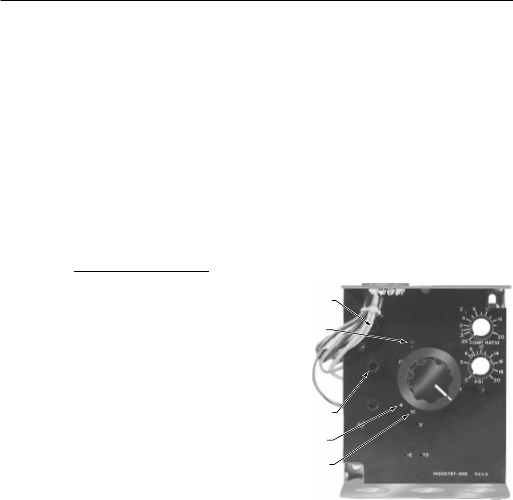
recalibrate the controller. Calibration potentiometers are
behind the three holes on the left side of the front panel, see
Figure 6. To compensate for main sensor and/or setpoint
potentiometer lead wires or calibration, adjust the middle
potentiometer R7 (Cal. Pot. No. 2) clockwise. This
compensates for leadwire length and a controlling
temperature which is lower than the setpoint. (3.5 degrees
of rotation per ohm of leadwire resistance or per degree
off-calibration).
To compensate for the compensation sensor leadwire
resistance, adjust the top left potentiometer R1 (Cal. Pot.
No. 1) clockwise. (3.2 degrees of rotation per ohm of
leadwire resistance or per degree off-calibration.) Cal. Pot.
No. 1 also can be used to vary the compensation start point
(temperature at which compensation affect is zero). The
factory compensation start point setting is 70F. Turning Cal.
Pot. No. 1 CCW lowers the compensation start point
temperature.
CHECKOUT AND TESTING
CHECKOUT
The only checkout ordinarily required is to slowly rotate the
Setpoint Adjustment through the total proportional band of the
device to determine if the output devices operate properly.
If the system does not function properly or the controller
appears to be out of calibration, proceed with the following
testing information.
TESTING
Before testing, be sure the Controller power supply (11 to
12 Vdc) is present at test point (+) and (–1) of R7500 models.
If the correct supply voltage is not available at these points,
check the power input device as indicated in the literature
accompanying the applicable unit.
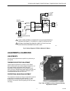
NO. 1 (R1)
CALIBRATION
POTENTIOMETER
NO. 2 (R7)
CALIBRATION
POTENTIOMETER
POWER SUPPLY
TEST POINT (+)
POWER SUPPLY
TEST POINT (-)
OUTPUT VOLTAGE
TEST POINT Y1
C8041
Fig. 6. Test Points and Calibration Adjustment Locations.
All R7500 series of controllers include test points on the left
side of the front panel (see Fig. 6). All Controllers have the
following points—
Y1 = Output voltage (yellow leadwire)
–1 = Power supply (–), (violet leadwire)
+ = Power supply (+), (orange leadwire)
Using the appropriate scale voltmeter, insert test probes into
appropriate holes for voltage checks.
95-7205
4