


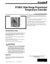
R7500C WIDE RANGE PROPORTIONAL TEMPERATURE CONTROLLER
WIRING
All wiring must agree with local electrical codes and
ordinances.
Since the Controller circuits are rated NEC Class 2, some
local codes allow open (no conduit) wiring.
Number 18 gage 1.0 mm insulated wire or two- or three-
conductor thermostat cable is acceptable for use with these
Controllers, except on long sensor or remote setpoint
potentiometer runs where a larger wire size should be used.
See Table 1.
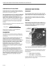
All control wiring connections to the Controller are made to
the 6-inch (152 mm), color-coded leadwires found bundled
under the cover. There are two orange wires to facilitate
connections to the converter and/or sensors.
Crimp type connectors are recommend for field connections
of the control wiring. Refer to job drawings for specific wiring
information. See Figures 2 through 4 for some typical
wiring diagrams.
IMPORTANT
Observe color-coding of wires when making connections.
R7503
BALCO
CONVERTER
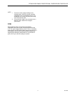
Table 1. Wire Resistance, Ohms per 1,000 Feet (304m).
Wire Gage
Wire Dia.
Size (mm)
Ohms/1000 ft
(304 m) of Wire
18 1.00 6.5
16 1.25 4.0
14 1.60 2.6
12 2.00 1.6
10 2.50 1.0
When determining proper wire size, remember there are two
wires to the sensor and the setpoint potentiometer. Double
the distance to the sensor or potentiometer to obtain the
proper wire length. Calibration of the controller will be
offset approximately 1F (0.5C) for every one ohm of lead
wire resistance.
BALCO MAIN SENSOR
MAIN SENSOR
BLACK
ORANGE
ORANGE
YELLOW
VIOLET
POWER
BROWN
1
O
Y
V
R7500
*
*
BALCO COMPENSATION
SENSOR
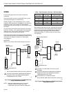
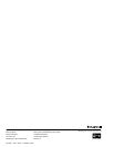
BOTH ORANGE WIRES ARE ELECTICALY IDENTICAL.
*
OPTIONAL DISCHARGE COMPENSATION SENSOR.
SUBSTITUTE WITH 500 OHM RESISTOR WHEN
COMPENSATION IS NOT USED.
C7828
Fig. 2. Typical Hookup Diagram of R7500C Model with
Integral Setpoint Adjustment.
NOTE: When the compensation sensor is not used,
substitute a 500-ohm resistor and set the
compensation ratio at the maximum setting (20).
M734K
M745J
14002385-008
REMOTE
SETPOINT
ADJUST
BLK
ORN
ORN
YEL
VIO
POWER
BRN
2
3
1
O
Y
V
D
Z
R
R7500
*
*
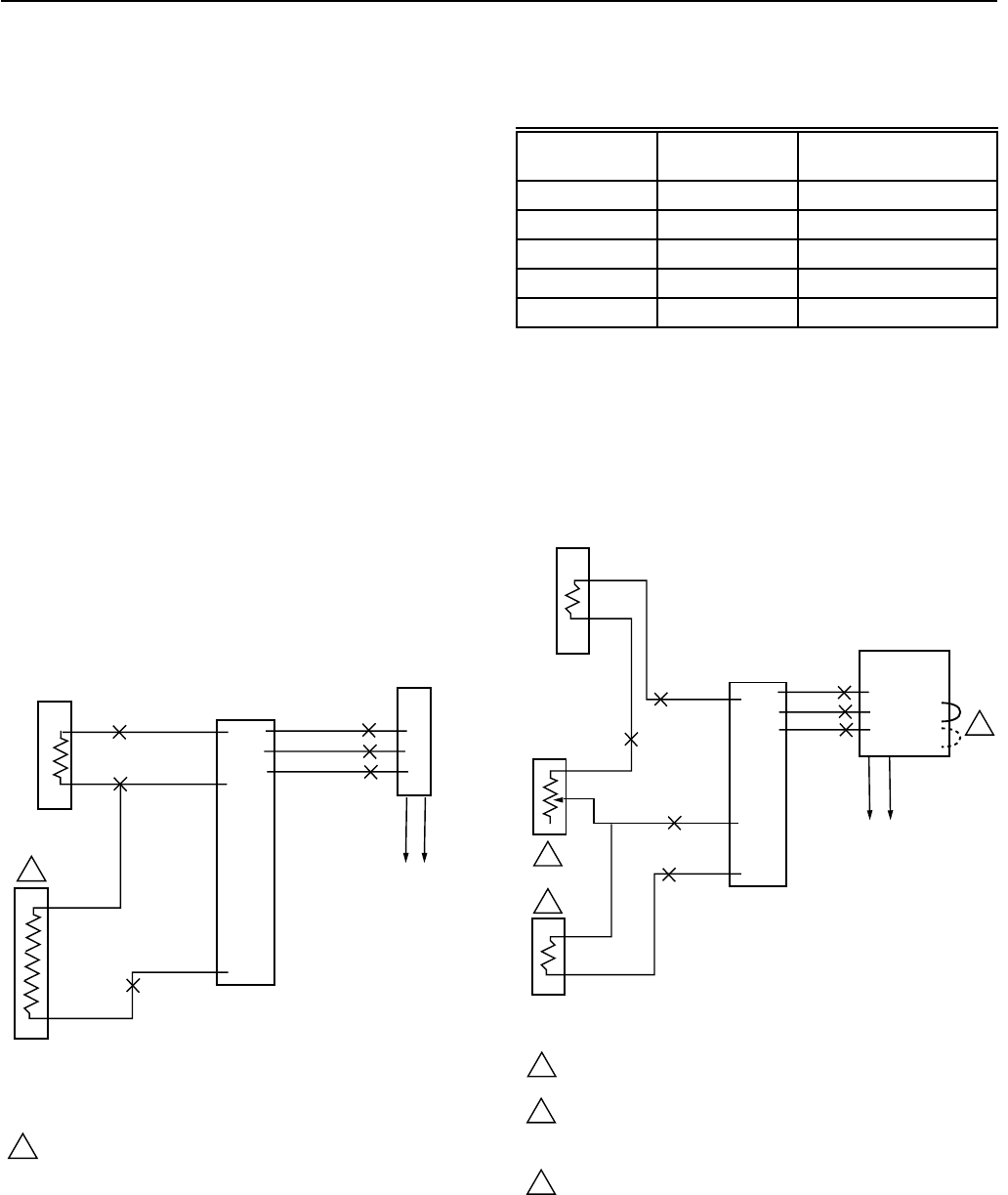
270Ω
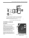
CONNECT Z-D FOR DIRECT ACTION; Z-R FOR
REVERSE.
OPTIONAL DISCHARGE COMPENSATION SENSOR.
SUBSTITUTE WITH 500 OHM RESISTOR WHEN
COMPENSATION IS NOT USED.
MOVE WIPER UP TO RAISE SETPOINT.
*
BOTH ORANGE WIRES ARE ELECTRICALY IDENTICAL.
C7829
BALCO COMPENSATION
SENSOR
3
1
2
Fig. 3. Typical Hookup Diagram of R7500C with Remote
Temperature Selector.
95-7205
2
1