


62-0131—2
4
Q7300L SERIES 2000 COMMERCIAL THERMOSTAT SUBBASE
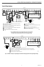
WIRING SUBBASE
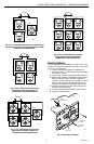
All wiring must comply with local electrical codes and ordinances. Follow equipment manufacturer wiring instructions when
available. Refer to Fig. 9 and 10 for typical hookups. A letter code is located near each terminal for identification. See
Table 3 for terminal descriptions and system action.
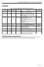
Table 3. Terminal Descriptions and Conditions.
CAUTION
Disconnect power before wiring to prevent
electrical shock or equipment damage.
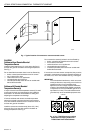
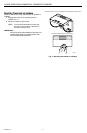
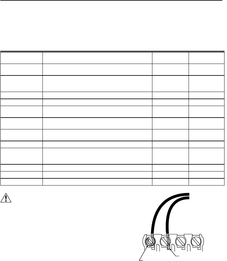
1. Loosen the terminal screws on the subbase and
connect the system wires. See Fig. 8.
IMPORTANT
Use 18-gauge, solid-conductor color-coded
thermostat cable for proper wiring. If using 18-
gauge stranded wire, no more than ten wires can
be used. Do not use larger than 18-gauge wire.
2. Securely tighten each terminal screw.
3. Push excess wire back into the hole.
4. Plug the hole with nonflammable insulation to
prevent drafts from affecting the thermostat.
NOTE: After wiring, check that all connections are tight
and secure. See Fig. 8. Loose or intermittent wire
connections cause inconsistent system operation.
Standard Terminal
Designations Typical Connection Function Terminal Type
A1, A2 Damper Control Relay. input, output 24V powered
contact
BM ML7984 Actuator connection. No call for heat, valve
closed during occupied periods and open during
unoccupied periods.
output —
C1, C2, C3, C4, C5 Communication input for T7147. — —
FC Fan control Transformer. input —
GH High speed fan output. Activated during calls for cooling. output 24V powered
contact
GL Low speed fan output. Activated on calls for heat and
fan On selection.
output 24V powered
contact
P1, P2 Pump Interlock Relay. Operates circulator pump in
hydronic heat or energizes conventional heat system.
input, output 24V powered
contact
R 24V System Transformer input —
RM ML7984 Actuator connection. No call for heat, valve
closed. Call for stage 1 heat, valve approximately one-
half open. Call for stage 2 heat, valve fully open.
——
T, T Remote sensor input for T7047 or T7147. — —
X Heating transformer common input —
Y Cool call 24V output on Y —
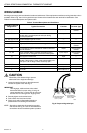
Fig. 8. Proper wiring technique.
M4826
FOR WRAPAROUND
INSERTION STRIP
7/16 IN. (11 MM).
FOR STRAIGHT
INSERTION STRIP
5/16 IN. (8 MM).