


69-0392—9
8
T874R THERMOSTATS AND Q674L SUBBASES
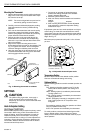
Mounting the Thermostat
1. Remove the thermostat cover by pulling the bottom
edge of the cover away from the base until it snaps
free from the cover clip.
NOTE: The cover is hinged at the top and can be
removed by pulling out at the bottom.
2. Carefully remove and discard polystyrene packing
insert that protects the mercury switches during
shipment.
3. Turn over the thermostat base and note the spring
fingers that engage the subbase contacts. Make
sure the spring fingers are
not
bent flat, preventing
proper electrical contact with the subbase.
4. Note the two tabs on the top inside edge of the
thermostat base. The tabs fit into corresponding
slots on the top of the subbase. Mount the thermo-
stat on the subbase.
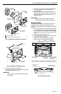
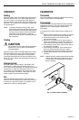
5. Align the two captive mounting screws in the
thermostat base with the posts on the subbase. See
Fig. 13. Tighten both screws.
Do not overtighten
screws
or damage to subbase posts can result.
6. Hang the upper edge of the thermostat cover on top
of the thermostat base and swing cover downward
until it engages with the cover clip.
THERMOSTAT
MOUNTING POST (2)
M3266
5
0
6
0
7
0
8
0
H
E
A
T
THERMOSTAT
MOUNTING SLOTS (2)
SUBBASE
THERMOSTAT
CAPTIVE MOUNTING
SCREWS (2)
Fig. 13. Mounting thermostat on subbase.
SETTINGS
CAUTION
On systems using a gas valve, never apply a
jumper across the valve coil terminals, even
temporarily. This can burn out the thermostat heat
anticipator(s).
Heat Anticipator Setting
(2nd Stage Y594R1243)
Set the heat anticipator scale to match the primary control
current draw. When using a T874 Thermostat with two
stages of heating, set the heat anticipator to match the
respective primary control current draw. If the primary
control nameplate has no rating or if further adjustment is
necessary, use the following procedure to determine the
current draw. Measure the current draw with the thermo-
stat removed and the power on.
1. Connect an ac ammeter of appropriate range
between the heating terminals of the subbase:
Stage 2: between W2 and R.
2. Move the system switch to HEAT.
3. After one minute, read the ammeter and record the
reading:
Stage 2: _______________amperes.
4. After mounting the thermostat, set the adjustable
heat anticipator to match the respective reading
measured in step 3.
If equipment cycles too fast, set the anticipator to a higher
current rating, not more than one-half division at a time,
and recheck cycle rate. Most conventional 2-stage heating
equipment is designed to operate at 3 cycles per hour per
stage. See Fig. 14.
Most heat pump systems should cycle 2-1/2 to 3 times
per hour.
Fig. 14. Adjustable heat anticipator scale.
Temperature Setting
Move the setpoint lever to the desired comfort position.
One lever controls both heating and cooling.
Subbase Setting
System switching positions control thermostat operation as
follows:
OFF: Heating and cooling systems are off. If the fan
switch is at the AUTO position, the cooling fan is
also off.
HEAT: Heating system is controlled by the thermostat.
Cooling system is off.
COOL: Cooling system is controlled by the thermostat.
Heating system is off.
EM.HT.: Emergency heat relay is energized on call for
heat. Cooling system is off. Compressor is de-
energized.
Fan switching positions control fan operation as follows:
ON: Fan operates continuously.
AUTO: Fan operates as controlled by the thermostat.
To switch positions, use thumb and index finger to slide
lever to desired position. Stop switch lever in detent
directly over the desired function indicator mark for proper
circuit operation.
1.2
.4
.6
.3
.2
.15
.12
.10
.8
MOVE INDICATOR TO
MATCH CURRENT RATING
OF PRIMARY CONTROL
M3684