


69-0392—9
2
T874R THERMOSTATS AND Q674L SUBBASES
OPERATION
On a 2-heat thermostat, the two stages of heat
make
sequentially as the temperature drops.
Make
refers to the
mercury switch initiating a call for heat or cool.
There is about 1° F (0.6° C) between stages so the sec-
ond stage makes only when the first stage can not handle
the load. The 1° F (0.6° C) is referred to as the
interstage
differential
.
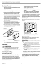
The light emitting diodes (LED) on the subbase light when
something specific happens within the system. When an
LED lights, refer to this list for the meaning:
EM. HT.: Emergency heat is operating. The compres-
sor has failed, and the heat pump is not operating.
LED lights when system switch is placed in the
EM.HT. position by the homeowner.
AUX.HT.: Auxiliary heat is operating, which means the
weather is so cold that the heat pump cannot handle
the load.
CHECK: System needs to be checked. See heating
sys-tem instructions for specific meaning.
NOTE: LEDs are not field replaceable or addable.
RECYCLING NOTICE
This control contains mercury in a sealed tube. Do n
ot
place control in the trash at the end of its useful life.
If this control is replacing a control that contains
mer-cury in a sealed tube, do
not
place your old
control in the trash.
Contact your local waste management authority for
instructions regarding recycling and the proper
disposal of this control, or of an old control
containing mercury in a sealed tube.
INSTALLATION
When Installing this Product…
1. Read these instructions carefully. Failure to follow
them could damage the product or cause a hazard-
ous condition.
2. Check the ratings given in the instructions and on
the product to make sure the product is suitable for
your application.
3. Installer must be a trained, experienced service
technician.
4. After installation is complete, check out product
operation as provided in these instructions.
CAUTION
1. Disconnect power supply to prevent electrical
shock or equipment damage.
2. To prevent interference with the thermostat
linkage, keep wire length to a minimum and
run wires as close as possible to the subbase.
3. Push excess wire back into the hole and plug
hole to prevent drafts from affecting thermo-
stat operation.
4. Do not overtighten thermostat captive
mounting screws because damage to
subbase threads can result.
5. Do not short across coil terminals on heating
relay or gas valve. This can burn out the
thermostat heat anticipator.
6. Never install more than one wire per terminal
unless factory-supplied jumper with spade
terminals is used.
IMPORTANT
Thermostats are calibrated at the factory using
subbase mounted at true level. Inaccurate
subbase leveling causes the actual temperature
to deviate from the setpoint temperature.
Location
Install the thermostat about 5 ft (1.5m) above the floor in
an area with good air circulation at average temperature.
Do not install the thermostat where it can be affected by:
— drafts or dead spots behind doors and in corners.
— hot or cold air from ducts.
— radiant heat from sun or appliances.
— concealed pipes and chimneys.
— unheated (uncooled) areas such as an outside wall
behind the thermostat.
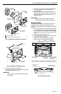
Mounting The Subbase
The thermostat subbase can be mounted on a vertical
outlet box, horizontal outlet box or directly on the wall.
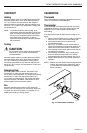
1. If you must mount the subbase on a vertical outlet
box, order Honeywell 193121A Adapter Assembly.
See Fig. 1. The assembly includes an adapter ring,
two screws and a cover plate to cover marks on the
wall. Install the ring and cover plate on the vertical
outlet box.
For a wall installation, hold subbase in position and
mark holes for anchors. See Fig. 2. Obtain wall
anchors locally. Be careful that the wires do not fall
back into the wall opening. Set aside subbase. Drill
two 3/16 in. (5 mm) holes and gently tap anchors
into the holes until flush with the wall.