


Settings
SUBBASE SETTING
The subbase switching positions control the system
operation as described below.
SYSTEM SWITCH (some subbases do not have all of the
following functions):
COOL—cooling system is automatically controlled
by the thermostat. Heating system is off.
OFF—both the heating and cooling systems are off. If
the fan switch is at AUTO position, the cooling fan
is also off.
HEAT—heating system is automatically controlled
by the thermostat. Cooling system is off.
FAN SWITCH:
ON—fan operates continuously.
AUTO—fan operates with cooling equipment as con-
trolled by the thermostat or with the heating equip-
ment as controlled by the plenum switch.
To move the subbase switches to the desired control
positions, use thumb and index finger to slide lever. Stop
lever must stop over desired function indicator position for
proper circuit operation.
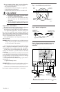
Fig. 4—Typical hookup for Q539H in heating-
cooling application with remote switching
required to select heating or cooling and to
provide automatic fan operation.
Q539H/T87F INTERNAL SCHEMATIC
T87F
TEMP.
FALL
R1
ADJUST-
ABLE
HEAT
ANTICIPATOR
FILTER
LIGHT
X
W Y
G
R
CLOGGED
FILTER SWITCH
OR COOLING
PANEL
CONNECTION
HEATING
RELAY OR
VALVE
COIL
COOLING
CONTACTOR
COIL
EXTERNAL
SWITCHING
FOR AUTO
FAN
FAN
RELAY
Z
2
1
1
X TERMINAL IS USED ON Q539 MODELS WITH
FACTORY-INSTALLED MALFUNCTION LIGHT.
W1
Y1
AUTO
FAN
ON
HEAT
COOL
REMOTE
SYSTEM
SWITCH
2
POWER SUPPLY. PROVIDE DISCONNECT
L2
L1
MEANS AND OVERLOAD PROTECTION AS REQUIRED.
(HOT)
M8833
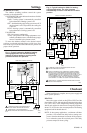
Fig. 5—Typical hookup for Q539J in heating-
cooling applications. Fan relay operates
automatically on heat or cool with fan in AUTO
position
Q539J/T87F INTERNAL SCHEMATIC
HEAT
OFF
COOL
HEAT
OFF
COOL
AUTO
FAN
ON
W
B R G
P
T87F
TEMP.
FALL
R1
ADJUST-
ABLE
HEAT
ANTICIPATOR
FILTER
LIGHT
X
Y
CLOGGED
FILTER SWITCH
OR COOLING
PANEL
CONNECTION
COMPRESSOR
RELAY
COOLING
DAMPER
MOTOR
FAN
RELAY
O
L1
(HOT)
L2
3
2
1
W1
Y1
ELECTRIC
HEAT
RELAY
HEATING
DAMPER
MOTOR
1
2
3
X TERMINAL IS USED ON Q539 MODELS WITH FACTORY-
INSTALLED MALFUNCTION LIGHT.
WITH NO O TERMONAL LOAD, THERMOSTAT CURRENT DURING
HEATING CYCLE VARIES DEPENDING ON WHETHER FAN SWITCH
IS IN THE ON OR AUTO POSITION. HEATER SHOULD BE SET FOR
COMBINED CURRENT LEVEL OF HEAT RELAY AND FAN RELAY COILS.
WITH O TERMINAL LOAD, SET THERMOSTAT HEAT ANTICIPATOR
TO ITS MAXIMUM SETTING. (LIMIT THE THERMOSTAT HEATING
LOAD CURRENT TO 0.8 AMPS TO ASSURE GOOD PERFORMANCE.)
POWER SUPPLY. PROVIDE DISCONNECT MEANS AND OVERLOAD
PROTECTION AS REQUIRED.
M8834
Checkout
When installation is complete, turn on power supply and
check system operation.
HEATING
Move the system switch on the Q539 to HEAT and the
fan switch to AUTO. Move the heating setpoint dial to about
6AC (10AF) above room temperature. Heating equipment
should start and the fan should run. Change the setpoint to
about 6AC (10AF) below the room temperature. The heating
equipment and fan should shut off.
NOTE: In heat pump applications, a minimum off-timer
provides a five-minute time delay before starting com-
pressor when the thermostat last turned off the compres-
sor, or when the system first received power. This delay
prevents compressor short cycling.
3 95-6486—9