


Do not mount the subbase where it may be affected by:
— drafts or dead spots behind doors or in corners.
— hot or cold air from ducts.
— radiant heat from the sun, fireplaces, or appliances.
— concealed pipes and chimneys.
— unheated (uncooled) areas such as an outside wall.
CAUTION
• Disconnect power supply to prevent electri-
cal shock or equipment damage.
• Do not short across coil terminals on relay,
this can burn out the thermostat heat
anticipator.
• Do not overtighten captive mounting screws
because damage to subbase threads can result.
MOUNTING AND WIRING
Disconnect power supply before beginning installation to
prevent electrical shock or equipment damage.
All wiring must comply with local codes and ordinances.
1. In replacement applications, check the existing sub-
base wires for cracked or frayed insulation. Replace any
wires in poor condition. If the wire is plastered into the wall,
make a hole next to the wires and loosen the wires so that the
wires can be pushed back into the wall later.
2. In new installations, run wiring (if necessary) to the
subbase location.
IMPORTANT: To prevent interference with the thermostat
linkage, keep wire length to a minimum and run wires
as close as possible to the subbase.
3. Connect the wires to the terminals inside the subbase.
Refer to equipment manufacturer instructions for Q539
wiring diagrams. If not available, refer to Fig. 1 through 5.
4. Push excess wire back through the hole and plug any
opening with insulation to prevent drafts that can affect
performance.
5. Loosely fasten the thermostat subbase to the wall with
a screw through the left mounting hole. Adjust the subbase so
it is approximately level and start the second screw through
the right mounting slot. Do not tighten.
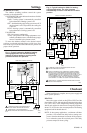
6. Level the thermostat subbase using a spirit level as
shown in Fig. 1.
7. Tighten mounting screws.
IMPORTANT: An incorrectly leveled subbase will cause
the temperature control to deviate from setpoint.
8. Mount and wire the thermostat to the thermostat sub-
base using the equipment manufacturer’s instructions.
Fig. 1—Level Q539 using a spirit level .
SPIRIT
LEVEL
LEVELIN
G
POSTS (2
)
MOUNTING
SLOTS
M3319A
O
PENING FOR
T
HERMOSTAT
W
IRING
Fig. 2—Barrier configuration.
FOR STRAIGHT
INSERTION–
STRIP 5/16 in. (8 mm)
FOR WRAPAROUND–
STRIP 7/16 in. (11 mm)
SUBBASE TERMINAL SCREW
M8831
BARRIER
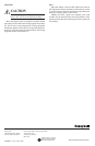
Fig. 3—Typical hookup for Q539A in heating-
cooling application with remote lockout
indication.
Q539A/T87F INTERNAL SCHEMATIC
T87F
TEMP.
FALL
R1
ADJUST-
ABLE
HEAT
ANTICIPATOR
FIXED COOL
ANTICIPATOR
LOCKOUT
INDICATOR
LIGHT
HEAT
OFF
COOL
HEAT
OFF
COOL
AUTO
FAN
ON
X RH W Y G RC
SWITCH
HEATING
CONTROL
COOLING
CONTROL
FAN
RELAY
HEATING
TRANSFORMER
COOLING
TRANSFORMER
L1L1
1
1
W1
Y1
L2 L2
(HOT) (HOT)
POWER SUPPLY. PROVIDE DISCONNECT MEANS AND OVERLOAD
PROTECTION AS REQUIRED.
M8832
95-6486—9 2
1