


3 60-0653—8
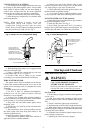
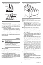
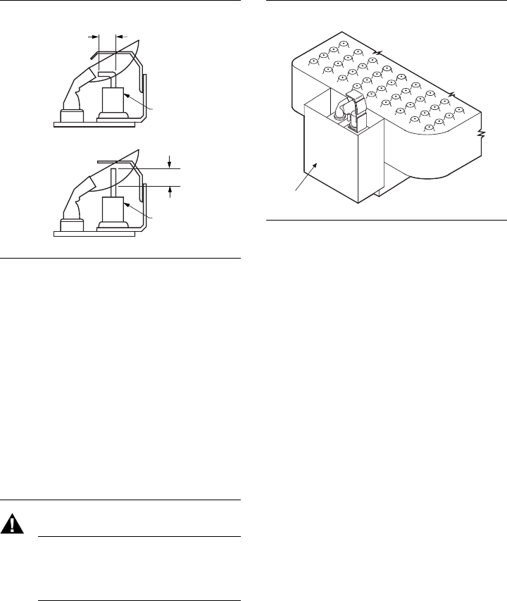
Fig. 5—Igniter-sensor tip must be in pilot flame. Fig. 6—Proper shielding of pilot flame.
M1273
TYPICAL
SHIELD
❏ Set the thermostat to call for heat.
❏ Watch the pilot burner during the ignition sequence.
See if:
• Ignition spark continues after the pilot is lit.
• The pilot lights and the spark stops, but main
burner does not light.
• S8600B,H; S86H only: The pilot lights, the spark
stops and main burner lights, but the system locks
out.
❏ If so, assure adequate flame current as follows:
• Turn off furnace at circuit breaker or fuse box.
• Clean the flame rod with emery cloth.
• Make sure electrical connections are clean and tight.
Replace damaged wire with moisture-resistant
no. 18 wire rated for continuous duty up to
221° F [105° C].
• Check for cracked ceramic insulator, which can
cause short to ground, and replace pilot burner/
igniter-sensor if necessary.
• At the gas control, disconnect main valve wire
from the TH or MV terminal.
• Turn on power and set thermostat to call for heat.
The pilot should light but the main burner will
remain off because the main valve actuator is dis-
connected.
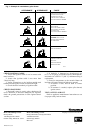
• Check the pilot flame. Make sure it is blue, steady
and envelops 3/8 to 1/2 in. [10 to 13 mm] of the
flame rod. See Fig. 7 for possible flame problems
and their causes.
• If necessary, adjust pilot flame by turning the pilot
adjustment screw on the gas control clockwise to
decrease or counterclockwise to increase pilot
flame. After adjustment, always replace pilot
adjustment cover screw and tighten firmly to
assure proper gas control operation.
• Set thermostat below room temperature to end call
for heat.
❏ Recheck ignition sequence as follows:
• Reconnect main valve wire.
• Set thermostat to call for heat.
• Watch ignition sequence at burner.
• If spark still does not stop after pilot lights, replace
ignition module.
• If main burner does not light or if main burner
lights but system locks out, check module, ground
wire, and gas control as described in control
module instructions.
3/8 TO 1/2 INCH
[10 TO 13 mm]
PROPER FLAME
ADJUSTMENT
IGNITER-SENSOR
3/8 TO 1/2 INCH
[10 TO 13 mm]
PROPER FLAME
ADJUSTMENT
IGNITER-SENSOR
M3777
Q373A
Q345A, Q348A-B, Q362A AND Q 381A
ADJUST PILOT FLAME
The pilot flame should envelop 3/8 to 1/2 in.
[10 to 13 mm] of the igniter-sensor tip. See Fig. 5. To
adjust pilot flame:
1. Turn off system by setting thermostat below
temperature to call for heat.
2. Disconnect lead to MV terminal on gas control.
3. Light pilot by setting thermostat to call for heat.
4. Remove pilot adjustment cover screw from gas
control.
5. Turn inner pilot adjustment screw clockwise to
decrease or counterclockwise to increase pilot flame.
6. Always replace pilot adjustment cover screw and
tighten firmly after completing adjustment to assure
pro-per operation.
Service
WARNING
FIRE OR EXPLOSION HAZARD
CAN CAUSE PROPERTY DAMAGE,
SEVERE INJURY, OR DEATH.
Perform Gas Leak Test anytime work is done to
the system.
PILOT OUTAGE
1. If pilot flame goes out during ignition, but is
pro-perly adjusted, recheck mounting and location
instructions in Location section.
2. Refer to ignition module instructions to check
wiring between igniter-sensor and ignition module or
between gas control and ignition module.
3. If all mounting and location instructions are fol-
lowed but pilot continues to go out, construct shielding
to protect pilot flame from main burner ignition and
extinction and drafts. See Fig. 6.
4. Check pilot and main burner lightoff.