


Startup and Checkout
PERFORM GAS LEAK TEST
WARNING
FIRE OR EXPLOSION HAZARD
CAN CAUSE PROPERTY DAMAGE,
SEVERE INJURY, OR DEATH.
Check for gas leaks with soap and water solu-
tion any time work is done on a gas system.
Gas Leak Test:
1. Ensure that gas supply is turned on at the appliance
service valve.
2. Paint pipe connections upstream of pilot burner
with rich soap and water solution. Bubbles indicate gas
leak.
3. If leak is detected, tighten pipe connections.
4. Set thermostat to call for heat to light main burner.
5. With main burner in operation, paint pipe joints
(including adapters) and gas control inlet and outlet with
rich soap and water solution.
6. If another leak is detected, tighten adapter screws,
joints, and pipe connections.
7. Replace part if leak cannot be stopped.
2
CONNECT PILOT GAS TUBING
1. Cut tubing to desired length and bend as necessary
for routing to pilot burner/igniter-sensor. Do not make
sharp bends or deform tubing. Do not bend tubing at
control after compression nut has been tightened
because this can result in gas leakage at connection.
2. Square off and remove burrs from end of tubing.
3. Push tubing into compression nut clearance hole
until tubing bottoms.
NOTE: When replacing a control, cut off old
compression fitting and replace with new
compression fitting provided with new pilot
burner. Never use old compression fitting because it
may not provide a gas-tight seal. See Fig. 3.
2. Connect one end of the ignition cable to stud
terminal on igniter-sensor using 1/4 in. [6 mm] diam-
eter snap-spring or cage-clips on cable ends.
3. Connect the other end of the ignition cable to the
igniter terminal on ignition module.
4. Use ceramic or plastic standoff insulators as nec-
essary to prevent cable from contacting metal surfaces.
INSTALL BLEED GAS TUBE (optional)
1. Route bleed tube from bleed tap on gas control to
the pilot burner/igniter-sensor.
2. Push clip into place. See Fig. 4.
3. Insert bleed gas tube until 3/8 in. [10 mm] to
tubing is above pilot burner/igniter-sensor bracket. Tip
of bleed gas tube must not extend into pilot flame.
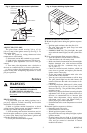
Fig. 3—Always use new compression fitting.
PILOT BURNER BODY
ON BRACKET OF PILOT
BURNER/IGNITER-SENSOR
TIGHTEN NUT ONE TURN
BEYOND FINGER TIGHT
COMPRESSION FITTING
BREAKS OFF AND CLINCHES
TUBING AS NUT IS TIGHTENED
TO GAS CONTROL
M3296
4. While holding tubing all the way in, engage threads
and turn until finger tight.
5. Using a wrench, turn compression nut one turn
beyond finger tight. Do not overtighten.
6. Connect other end of tubing to gas control
according to gas control manufacturer instructions.
WIRE IGNITER-SENSOR
The igniter-sensor must be mounted on the burner.
Connect the control module ground wire to one of the
igniter-sensor mounting screws to complete the system
grounding.
Connect ground wire as follows:
1. Use 221° F [105° C] minimum thermoplastic-
insulated wire for the ground leadwire (asbestos
insulation is not acceptable).
2. A male 1/4 in. [6 mm] quick-connect terminal is
provided on Honeywell ignition modules. Fasten female
quick-connect to wire end at ignition module.
3. Strip other end and fasten under igniter-sensor
mounting screw.
4. If necessary, use shield to protect lead from radi-
ant heat of burner.
5. The pilot burner serves as the grounding area for
the flame signal. Run lead from pilot burner to the
common ground selected.
Connect the ignition cable as follows:
1. The high tension ignition cable must conform to
applicable local or national standards.
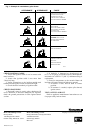
Fig. 4—Install bleed gas tube.
THIS DIMENSION SHOULD
BE MAXIMUM OF 3/8 INCH
[9.5 mm] WHEN BLEED
TUBE IS IN FINAL
POSITION.
BLEED TUBE CLIP
M1261
1/8 IN. STEEL TUBING