


PILOT TURNDOWN TEST
(30 mV safety control systems)
The Pilot Turndown Test assures that the pilot flame
ignites the main burner within four seconds from the time gas
reaches the main burner. In this test, the pilot flame is just
sufficient enough to hold in the power unit or just above the
point of flame extinction (whichever occurs at a higher pilot
gas flow rate).
1. With the pilot and main burner operating, shut off the
main burner by either lowering the thermostat temperature
setting or turning the gas control knob to the PILOT position.
NOTE: If using a Honeywell W129A Millivoltmeter, turn
the pilot gas adjustment screw until the thermocouple
open circuit voltage is 2 mV. Omit steps 2,3, and 4 and
proceed with step 5.
2. Turn the p ilot gas adjustment screw clockwise until
the pilot begins to decrease in size. Then, turn the pilot gas
adjustment screw clockwise 1/4 turn a time (waiting
one minute between each turn to allow the thermocouple to
cool) until safety shutoff power unit just drops, causing safety
shutdown.
5 69-0519—3
3. Turn pilot gas adjustment screw counterclockwise
slightly.
4. Relight pilot burner. The power unit should hold in.
5. Turn gas control knob to ON position and set thermo-
stat temperature setting above room temperature. Main burner
should light within four seconds without flame rollout. If not,
check pilot mounting and location instructions in Location
section and repeat Pilot Turndown Test.
6. Readjust pilot burner flame. See Adjust Pilot Flame
section.
EFFECTIVE IGNITION TEST (750 mV SYSTEMS)
The Effective Ignition Test assures that the pilot flame
ignites the main burner within four seconds from the time gas
reaches the main burner. In this test, the pilot flame is just
sufficient to open the main gas valve.
1. Light the main burner according to the appliance
manufacturer’s instructions and allow to burn at least five
minutes.
2. Remove one thermostat lead (TH) at the gas control
terminal.
3. Using the pilot gas adjustment screw, decrease the
pilot flame until it begins to pull away from the thermopile.
Allow thermopile to cool for one minute.
4. Temporarily jumper the thermostat terminals (TH) on
the gas control.
5. If the main burner ignites, reduce the pilot flame by
turning the pilot adjustment screw 1/4 turn at a time until the
valve fails to pull in. Allow the thermocouple to cool at least
one minute between each reduction in the pilot flame level.
6. Increase the pilot flame just enough to pull in the gas
control main valve.
7. Jumper the thermostat terminals. The main burner
should light within four seconds and without flame roll-out.
If it does not, check the Location and Mounting instructions
on page 1 and repeat steps 1 through 6.
8. If main burner still does not light, replace thermopile
and repeat steps 1 through 6.
9. Remove the jumper to shut off the main burner.
10. Readjust pilot burner flame. See Adjust Pilot Flame
section.
11. Reconnect the thermopile lead and ensure all connec-
tions are correct and the system is functioning properly.
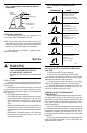
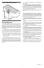
Fig. 10—Proper shielding of pilot flame.
M1273
TYPICAL
SHIELD