


Service
WARNING
FIRE OR EXPLOSION HAZARD
CAN CAUSE PROPERTY DAMAGE,
SEVERE INJURY, OR DEATH
Perform Gas Leak Test anytime work is done to the
system.
PILOT OUTAGE
1. If pilot flame goes out during normal operation, but is
properly adjusted, recheck Mounting and Location instruc-
tions on page 1.
2. If all mounting and location instructions are followed
but pilot continues to go out, construct shielding to protect
pilot flame from main burner ignition and extinction and
drafts. See Fig. 9.
3. Check pilot flame characteristics.
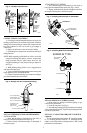
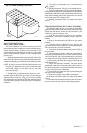
• Check the pilot flame with the main burner operating.
• Ensure the pilot flame continuously covers the tip of
the thermocouple or thermopile, the spark gap and
3/8 to 1/2 in. [10 to 13 mm] of the ground rod. See
Fig. 8.
• Ensure the pilot flame is blue (a yellow tipped flame is
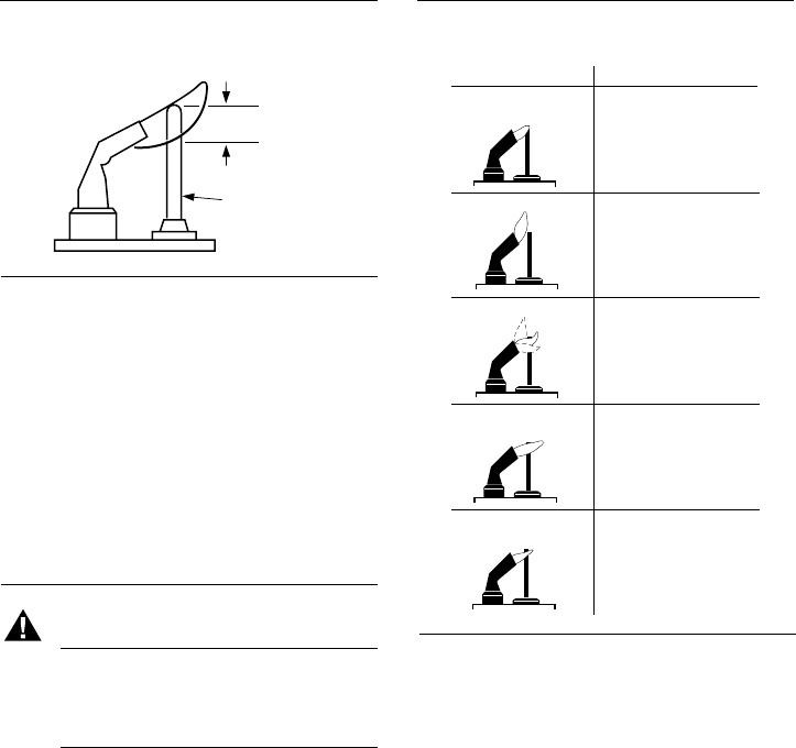
acceptable on LP systems), soft and steady. See Fig. 9
for examples of possible pilot flame problems and their
causes.
• If pilot burner is damaged, replace it with an identical
pilot burner and mount and position in the same
location and orientation.
4
Fig. 8—Thermocouple or thermopile tip must be
in pilot flame.
THERMOCOUPLE
OR THERMOPILE
PROPER
FLAME
ADJUSTMENT
3/8 TO 1/2 INCH
[10 TO 13 MILLIMETRES]
M1973A
IGNITE PILOT BURNER
1. Before lighting pilot burner, turn thermostat to its
lowest setting. Wait for unburned gas to vent.
NOTE: LP gas is heavier than air and will not vent upward.
Smell for LP gas next to floor. If you smell gas, shut off the
main valve in the gas piping, or, ON LP, AT THE TANK.
Perform Gas Leak Test to recheck all connections.
2. Light pilot burner according to appliance manu-
facturer’s instructions.
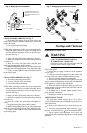
Fig. 9—Examples of unsatisfactory pilot
flames.
PILOTSTAT SAFETY CONTROL POWER UNIT
FAILURE
1. Ensure pilot flame is properly adjusted.
2. Ensure power unit connections clean and tight.
3. If power unit still fails to hold in, use the W129A
Millivoltmeter to obtain the open and closed circuit voltage
generated by the thermocouple or generator.
4. Compare measured open and closed circuit voltage
values to Acceptable Range Charts in W129A Manual.
5. If W129A Millivoltmeter or other meter is not avail-
able, replace thermocouple or thermopile. If this does not
correct the condition, replace power unit.
THERMOCOUPLE OR THERMOPILE
PERFORMANCE
Thermocouples and thermopiles require proper tempera-
ture differential between the hot-junction (tip) and cold-
junction (base) to provide satisfactory operation of gas con-
trols. Thermocouples and thermopiles perform less effec-
tively when exposed to excessive cold-junction or hot-
junction temperatures.
Excessive cold-junction temperatures can be caused by
heat radiation from adjacent surfaces or high ambient air
temperatures. Excessive cold-junction temperatures can be
eliminated by shielding the pilot flame, see Fig. 10, or
constructing a baffle to direct secondary air over the pilot
burner base.
Excessive hot-junction temperatures can be eliminated by
proper pilot flame adjustment. To adjust pilot flame, see
Adjust Pilot Flame section.
LAZY YELLOW FLAME
WAVING BLUE FLAME
NOISY LIFTING BLOWING FLAME
HARD SHARP FLAME
SMALL BLUE FLAME
CHECK FOR LACK OF GAS FROM:
• CLOGGED ORIFICE FILTER
• CLOGGED PILOT FILTER
• LOW GAS SUPPLY PRESSURE
• PILOT ADJUSTMENT AT MINIMUM
CHECK FOR LACK OF AIR FROM:
• LARGE ORIFICE
• DIRTY LINT SCREEN, IF USED
• DIRTY PRIMARY AIR OPENING,
IF THERE IS ONE
• PILOT ADJUSTMENT AT MINIMUM
CHECK FOR:
• EXCESSIVE DRAFT AT PILOT
LOCATION
• RECIRCULATING PRODUCTS
OF COMBUSTION
CHECK FOR:
• HIGH GAS PRESSURE
THIS FLAME IS CHARACTERISTIC
OF MANUFACTURED GAS
CHECK FOR:
• HIGH GAS PRESSURE
• ORIFICE TOO SMALL
M3272
APPEARANCE
CAUSE