


PC8900A CONTROL PANEL
4
69-0893—1
Home and Building Control
Honeywell Inc.
1985 Douglas Drive North
Golden Valley, MN 55422
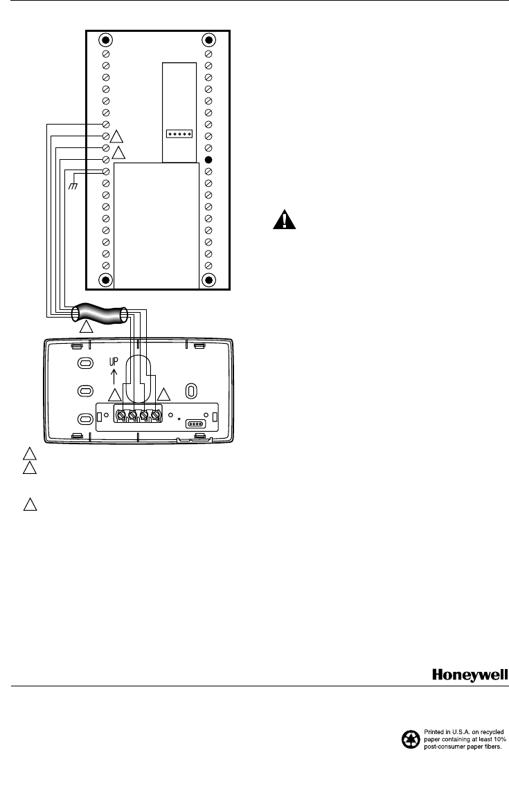
M7519
1234
GND
W8900
1
2
3
4
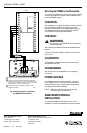
NOTE WHICH COLOR WIRE IS ATTACHED TO EACH TERMINAL.
FOUR WIRES ARE REQUIRED FOR PROPER OPERATION.
IF FEWER THAN FOUR ARE AVAILABLE, ADDITIONAL WIRES
MUST BE RUN TO PC8900 LOCATION. IF MORE THAN FOUR
ARE AVAILABLE, TAPE OFF UNUSED WIRES.
IF SHIELDED CABLE IS REQUIRED, GROUND TO GND
TERMINAL ON W8900.
1
1
1
2
2
2
3
3
Fig. 4. Wiring Diagram for PC8900 to
the W8900 Remote Module.
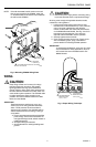
Mounting the PC8900 on the Wiring Plate
To mount the PC8900 on the wiring plate, engage the tabs
on the wiring plate with the back of the PC8900 and then
press the PC8900 to latch.
OPERATION
The PC8900 is not a typical thermostat. It senses tempera-
ture and humidity conditions in the living space and
transfers the information to the W8900 Remote Module.
The W8900 activates the proper equipment based on
room conditions and programmed settings.
CHECKOUT
WARNING
Do
not
jumper any PC8900 wires in an attempt to
activate equipment.
See checkout procedures included with W8900 Remote
Module.
To test for 24V at the PC8900, measure between termi-
nals 1 and 4.
CALIBRATION
The PC8900 is calibrated at the factory and cannot be
recalibrated in the field.
PROGRAMMING
See Owner’s Guide, form 69-0891, for programming
instructions.
POWER OUTAGES
The PC8900 requires no backup batteries. In event of
power outage, the time of day and day are retained for
approximately six hours. Program times, temperatures,
and settings will be held indefinitely.
NOTE: When power is restored, the time and day
information must be re-entered.
W8900 REMOTE MODULE
INSTALLATION
To install the W8900 Remote Module, refer to form
69-0894 for instructions packed with the remote module.
69-0893—1 J.H. Rev. 5-95
Home and Building Control
Honeywell Limited-Honeywell Limitée
35 Dynamic Drive
Scarborough, Ontario
M1V 4Z9