


PC8900A CONTROL PANEL
69-0893—1
3
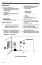
NOTE: If the old thermostat has left marks on the wall
that are not covered by the PC8900, order part
no. 205224A Wall Cover Plate to mount between
the wall and the PC8900.
Fig. 2. Mounting PC8900 Wiring Plate.
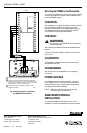
WIRING
CAUTION
Keep wiring at least one foot away from large
inductive loads such as motors, line starters,
lightning ballasts and large power distribution
panels. Failure to follow these wiring practices can
introduce electrical interference (noise), which can
cause erratic system operation. Use shielded cable
to reduce interference when rerouting is not
possible. Ground the shielded cable to the GND
terminal on the W8900.
IMPORTANT
Erratic temperature readings can occur as a
result of any of the wiring practices described
below. These practices must be avoided to
assure proper operation. Use shielded cable to
reduce interference when rerouting of wiring is
not possible.
a. Do not route thermostat wiring with building
power wiring, next to control contactors or
near light dimming circuits, electric motors or
welding equipment.
b. Avoid poor wiring connections.
c. Avoid intermittent or missing building earth
ground.
CAUTION
Disconnect power supply before connecting wiring
to prevent electrical shock or equipment damage.
All wiring must comply with applicable electrical codes,
ordinances, and regulations.
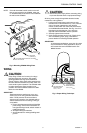
1. Loosen the terminal screws and insert one wire
beneath each numbered terminal (1,2,3,4). Note the
color of wire that is attached to each terminal
number to later match the colors with the terminals
on the W8900 Remote Module. See Fig. 3 and 4 for
technique and wiring diagram. Four wires are
required at the thermostat to assure operation.
2. Securely tighten screw terminals.
3. Push excess wire back into the hole. Plug the hole
with nonhardening caulk, putty or insulation to
prevent drafts from affecting PC8900 operation.
IMPORTANT
In replacement applications, more than four wires
may be available. In these applications, tape off
the unused wires at the PC8900 location and
W8900 location.
M7518
FOR WRAPAROUND
INSERTION STRIP
7/16 in. (11mm).
FOR STRAIGHT
INSERTION STRIP
5/16 in. (8mm).
Fig. 3. Proper Wiring Technique.
WIRES
THROUGH WALL
WALL
MOUNTING
HOLES (4)
MOUNTING
SCREWS (3)
USE THREE MOUNTING HOLES THAT BEST
FIT APPLICATION
1
1
M4466
1
WALL
ANCHORS
(3)