


L91A,B,D PROPORTIONING PRESSURETROL
®
CONTROLLERS
7 60-2152—08
point). The L91B settings provide system modulation between
70 and 75 psi or between 75 and 80 psi, depending on the
exact setting of the L91B main scale setpoint.
Due to device tolerances, the scaleplate settings are
approximate and, therefore, the settings should be fine-tuned
with the system operating.
Proportioning Range (L91B,D Only)
Adjust the proportioning range (throttling range) by turning the
proportioning range adjusting screw (Fig. 6) on the top of the
case until the proportioning range setting indicator is at the
desired value. The proportioning range scale is graduated from
A to F with a MIN (minimum) value below A. The value of each
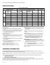
division depends on the operating range of the controller. Refer
to Table 2 in the Specifications section.
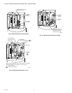
Typical Operation
Pressure variations cause the bellows to expand or contract.
Linkage between the bellows and the potentiometer wiper
causes the wiper to move across the potentiometer windings.
This varies the resistance between R and B, and between R
and W, causing an unbalance in the circuit connected to the
controller. See Fig 7.
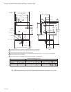
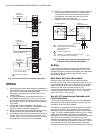
Fig. 5. L91A,B,D operating points.
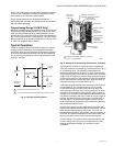
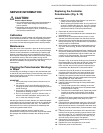
Fig. 6. Setting L91 Proportioning Pressuretrol
®
Controller.
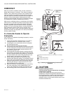
A proportioning controller is used most often to regulate the
firing rate of a burner by controlling a modulating motor (Fig. 4)
or a modulating valve. The controller potentiometer, the
feedback potentiometer in the motor (or in the valve actuator),
and a balancing relay in the motor (or actuator) form an electric
bridge circuit. As long as the pressure of the controlled medium
remains at the setpoint of the controller, the circuit is balanced;
that is, equal the relay contacts are open. When the circuit is
balanced, the motor (or actuator) does not run.
If the pressure of the medium rises, the wiper in the controller
moves toward W. This unbalances the circuit, so a larger
current flows through one side of the balancing relay. The
close contacts in the relay make, causing the motor (or valve
actuator) to drive toward its closed position. As the motor (or
actuator) runs, the wiper on the feedback potentiometer moves
in a direction to balance the circuit. When the circuit is again in
balance, the balancing relay contacts open and the motor (or
actuator) stops. The valves and dampers connected to the
motor or actuator will be partially closed, decreasing the firing
rate and reducing the pressure.
Similarly, if the pressure of the controlled medium falls, the
wiper on the controller potentiometer moves toward B, and the
open contacts in the balancing relay make. The motor (or
actuator) drives toward its open position until circuit balance is
achieved. The valves and dampers will be opened wider and
the firing rate will increase, thus increasing the pressure.
A small change in the pressure of the controlled medium will
cause a change in the firing rate to compensate for it, thus
keeping the pressure constant. This process is called
modulation.
M8519A
1
1
2
2
PROPORTIONING
RANGE
(WIPER)
POTENTIOMTER
LOW-FIRE
(CLOSED)
HIGH-FIRE
(OPEN)
MAIN SCALE
SETPOINT
B
W
R
PRESSURE
RISE
FIXED ON L91A; ADJUSTABLE ON L91B,D.
L91D HAS TWO POTENTIOMETERS OPERATING IN UNISION.
M8525
PROPORTIONING RANGE
ADJUSTING SCREW (L91B,D ONLY)
CONTROLLER
POTENTIOMETER
MAIN SCALE
ADJUSTING
SCREW
WIPER ARM(S)
PROPORTIONING
RANGE
SCALEPLATE
(L19B,D ONLY)
PROPORTIONING
RANGE SETTING
INDICATOR
(L91B,D ONLY)
TERMINAL BLOCK
BELLOWS
HOUSING
MAIN
SCALEPLATE
MAIN SCALE
SETTING
INDICATOR
1 KNURLED ADJUSTMENT KNOB ON 10 TO 300 PSI
[0.07 TO 2.07 MPa] MODELS.
1