


L91A,B,D PROPORTIONING PRESSURETROL
®
CONTROLLERS
5 60-2152—08
INSTALLATION
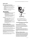
When Installing This Product...
1. Read these instructions carefully. Failure to follow them
could damage the product or cause a hazardous
condition.
2. Check the ratings given in the instructions and on the
product to make sure the product is suitable for your
application.
3. Installer must be a trained, experienced service
technician.
4. After installation is complete, check out product opera-
tion as provided in these instructions.
WARNING
Electrical Shock Hazard.
Can cause severe injury, death or property damage.
1. Disconnect power supply before beginning
installation to prevent electrical shock and
equipment damage.
2. When using the controller with a compressor, install
a dampening device (such as a needle valve,
header, or surge tank) to dampen pulsations that can
damage the controller or reduce its life.
IMPORTANT
1. Locate the controller where the ambient temperature
will not exceed 150° F (66° C).
2. When the controller is used on a boiler, be sure to
connect a steam trap (siphon loop) between the
controller and the boiler.
3. Before installing controller, be sure the siphon loop
has enough water in it to fill lower trap.
4. Use pipe compound sparingly to avoid clogging the
hole in the pipe or bellows fitting.
5. Do not tighten the controller by hand by holding onto
the case and turning it.
Location and Mounting
When used with steam boilers, always mount the controller
above the water line in the boiler. A steam trap (siphon loop)
must always be connected between the controller and the
boiler (Fig. 2) to prevent boiler scale and corrosive vapors from
attacking the bellows. Before installing controller, be sure the
siphon loop has enough water in it to fill lower trap.
The controller can be mounted (1) beside the pressure gauge,
(2) in a fitting on the boiler provided by the manufacturer, or (3)
at a remote location in case of excessive vibration.
Make all pipe connections in accordance with approved
standards. Use only a small amount of pipe compound to seal
the connection joints. Excess pipe compound may clog the
small hole in the fitting and prevent the controller from
operating properly.
To avoid leaks and damage to the case, use a parallel jaw
wrench on the controller fitting. Do not tighten the controller by
hand by holding onto the case and turning it.
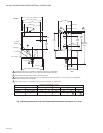
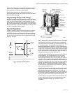
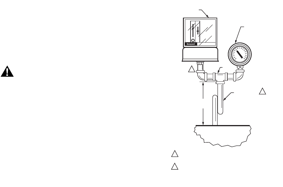
Fig. 2. Approximate dimensions in in. (mm) for mounting
L91 Pressuretrol
®
Controller beside Pressure Gauge on
Steam Trap (Siphon Loop).
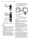
Mounting Beside a Pressure Gauge
To mount the controller beside a pressure gauge (Fig. 2),
remove the gauge. In its place, install a steam trap (siphon
loop) with a tee on top. Using elbows and pipe nipples, mount
the controller and pressure gauge on the ends of the tee.
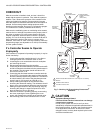
Mounting on a Boiler
If it is not convenient to mount the controller beside the
pressure gauge, install a steam trap (siphon loop) in the fitting
provided by the boiler manufacturer. If there is no fitting, mount
the steam trap at a location recommended by the boiler
manufacturer. Screw the controller directly to the steam trap, if
possible.
Mounting at a Remote Location
If there is excessive vibration at the boiler that may adversely
affect the operation of the controller, mount the controller at a
remote location. All piping from the boiler must be suitable and
solidly mounted. The piping must be properly pitched to drain
all condensation back to the boiler. If this causes the controller
to be located at an inconvenient height (on large boilers), it
may be mounted at a lower level if the connecting piping is
filled with clean water. A steam trap (siphon loop) must be
mounted between the remote piping and the controller.
PRESSURETOL
4-1/2 (114) TO
5-1/2 (140)
BOILER
STEAM TRAP
(SIPHON LOOP)
TEE
PRESSURE
GAUGE
L91
PRESSURETROL
CONTROLLER
M23884
2
1
1
2
50024585-001 STEAM TRAP IS A 1/4 IN. BRASS PIPE WITH
1/4 - 18 NPT EXTERNAL TRHEADS ON BOTH ENDS.
FITTING ON BELLOWS HAS 1/4-18 NPT EXTERNAL THREADS
ON 0 TO 16 OZ/SQ. IN. AND 0 TO 15 PSI MODELS; INTERNAL
THREADS ON ALL OTHER MODELS. SOME MODELS ARE
ALSO AVAILABLE WITH 1/4-19 BSP-TR INTERNAL THREADS;
SEE TABLE 1.