


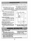
LENGTH OF ELEMENT (in inches) [millimeters] :
Self-supporting model-10 [254] (total length of
element).
Capillary models-24 [609.6], 36 [914.4], and 54
[ 1371.61 (flexible capillary length). Add 6 [ 152.41
inches for total length including sensing element.
SENSING ELEMENT: Liquid-filled.
ADJUSTMENT MEANS: Indicators are inside cover.
MOUNTING MEANS: Two holes in backplate.
DIMENSIONS: See Fig. 1.
FINISH: Gray.
UNDERWRITERS LABORATORIES INC COMPO-
NENT RECOGNIZED: File No. MP466, Guide No.
MBPR-2.
CANADIAN STANDARDS ASSOCIATION CERTI-
FIED: File No. LR1620, Guide No. 400-E-0.
OPTIONAL SPECIFICATION: L4017A Combination
Fan and Limit Control with fan-off scale. Unit has
fixed fan and limit differentials. Fan-on setting is
fixed at 33 F [19 C] above fan-off setting. With case
and cover.
ACCESSORY: Adapter plate bag assembly, Part No.
21136E, to match mounting holes of competitive
devices.
1. Installer must be a trained, experienced
serviceman.
2. Disconnect electricity before connecting wiring
to prevent electrical shock or equipment
damage.
3. Conduct a thorough checkout after the instal-
lation is complete.
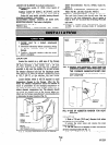
LOCATION
Locate the control on a solid area of the furnace
casing or jacket or on the discharge plenum. The stand-
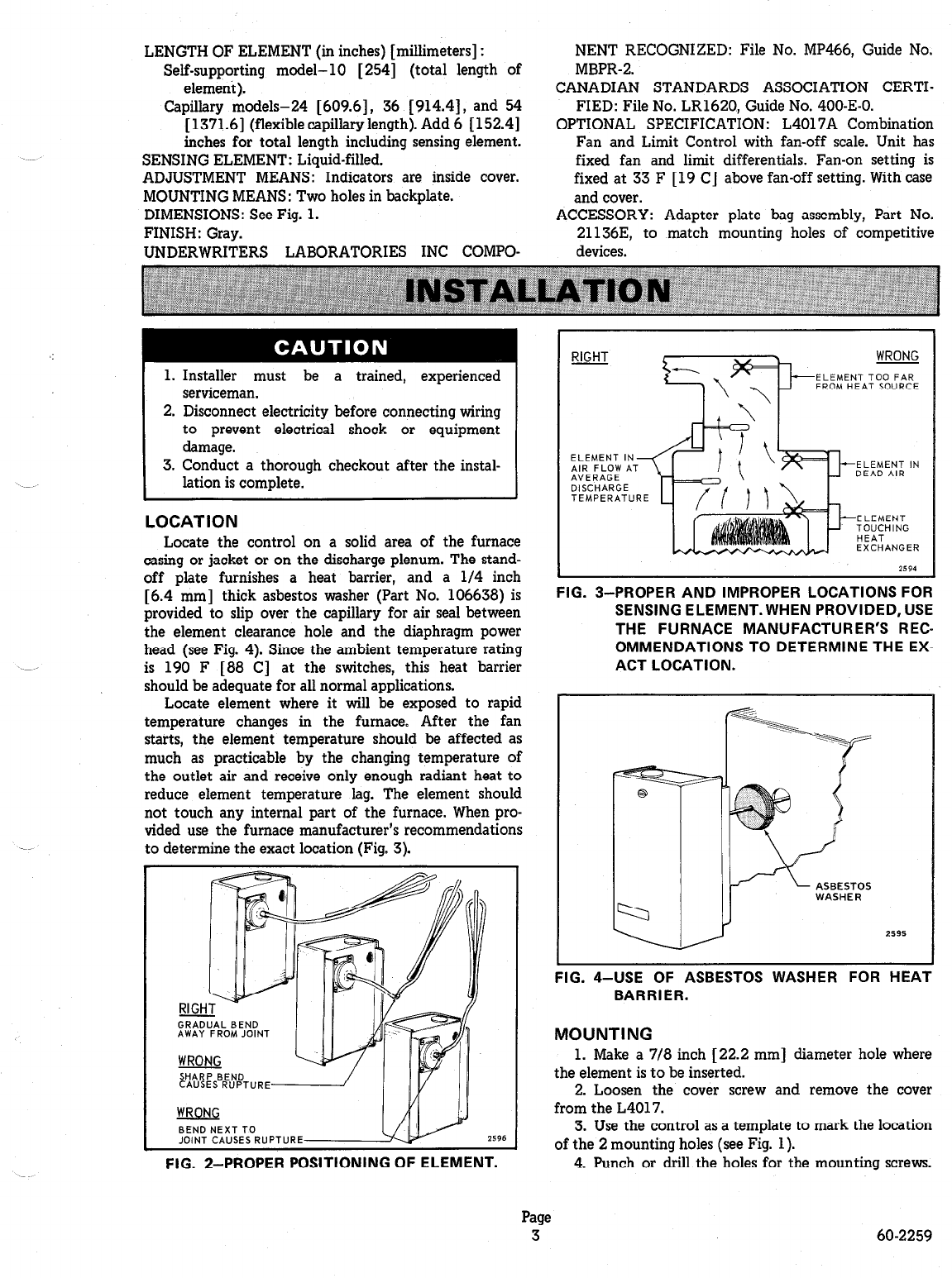
off plate furnishes a heat barrier, and a l/4 inch
[6.4 mm] thick asbestos washer (Part No. 106638) is
provided to slip over the capillary for air seal between
the element clearance hole and the diaphragm power
head (see Fig. 4). Since the ambient temperature rating
is 190 F [88 C] at the switches, this heat barrier
should be adequate for all normal applications.
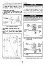
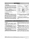
Locate element where it will be exposed to rapid
temperature changes in the furnace. After the fan
starts, the element temperature should be affected as
much as practicable by the changing temperature of
the outlet air and receive only enough radiant heat to
reduce element temperature lag. The element should
not touch any internal part of the furnace. When pro-
vided use the furnace manufacturer’s recommendations
to determine the exact location (Fig- 3).
SHARP BEND
CAUSES RUPTURE
WRONG
BENDNEXTTO
JOINT CAUSES RUPTURE
2596
FIG. 2-PROPER POSITIONING OF ELEMENT.
WRONG
ELEMENT TOO FAR
FROM HEAT SOURCE
ELEMENT I
AIR FLOW
ELEMENT IN
AVERAGE
DEAD AIR
DISCHARGE
TEMPERATURE
ELEMENT
‘,~~$“‘“”
EXCHANGER
FIG. 3-PROPER AND IMPROPER LOCATIONS FOR
SENSING ELEMENT. WHEN PROVIDED, USE
THE FURNACE MANUFACTURER’S REC-
OMMENDATIONS TO DETERMINE THE EX-
ACT LOCATION.
FIG. 4-USE OF ASBESTOS WASHER FOR HEAT
BARRIER.
MOUNTING
1. Make a 7/8 inch [ 22.2 mm] diameter hole where
the element is to be inserted.
2. Loosen the cover screw and remove the cover
from the L4017.
3. Use the control as a template to mark the location
of the 2 mounting holes (see Fig. 1).
4. Punch or drill the holes for the mounting screws.
Page
3
60-2259