


L4006,7,8; L6006,7,8 AQUASTAT
®
CONTROLLERS
60-2104—10 8
INSTALLATION
When Installing This Product…
1. Read these instructions carefully. Failure to follow them
could damage the product or cause a hazardous
condition.
2. Check the ratings given in the instructions and on the
product to make sure the product is suitable for your
application.
3. Installer must be a trained, experienced service
technician.
4. After installation is complete, check product operation as
provided in these instructions.
WARNING
Explosion Hazard.
Can cause serious injury, death or property
damage.
This product is intended for use only in systems with a
pressure relief valve.
WARNING
Electrical Shock Hazard.
Can cause serious injury or death.
Disconnect power supply before beginning installation
to prevent electrical shock or equipment damage.
CAUTION
Equipment Damage Hazard.
Use of incorrect device or improper installation can
damage the system.
1. Do not replace immersion-type Aquastat Controller
with strap-on Aquastat Controller.
2. Do not secure draw nut so tightly that retainer clamp
can collapse tubing.
IMPORTANT
1. Terminals on these Aquastat relays are approved for
copper wire only.
2. Controller may be used with or without immersion
well. If used, well must snugly fit sensing bulb for best
thermal response. Insert bulb until it rests against the
bottom of the well. Use well of correct length and
bend the tubing, if necessary, to provide enough force
to hold the bulb against the bottom of the well. Avoid
making a sharp bend in the tubing as it can produce a
break in the tubing and cause loss of fill. This
condition causes the High and Low Limit controls to
be made continuously.
3. If well does not snugly fit on bulb, use the heat-
conductive compound, included with Super Tradeline
and Tradeline models, as follows: Fold the plastic bag
of compound lengthwise and twist gently. Snip the
end of the bag and insert into the well. Slowly pull out
the bag while squeezing firmly to distribute compound
evenly in the well. Insert the bulb into the well. Bend
the tubing, if necessary, to provide force to hold the
bulb against the bottom of the well and to hold the
outer end of the bulb firmly in contact with the side of
the well. Wipe off excess compound.
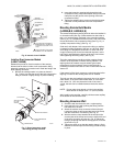
The manufacturer usually provides a tapping for insertion of
the controller sensing element. This tapping is located at a
point where typical water temperature can be measured.
Depending on the model, the element is inserted in an
immersion well, through a boiler fitting, or directly immersed.
Installation should be made by a qualified service technician.
Follow the instructions furnished by the system manufacturer, if
available. Otherwise, refer to appropriate procedure listed
below.
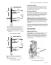
Mounting Immersion Well and Direct
Immersion Models (L4006A,B,C,E,G;
L4007A,B; L6006A,B; L6007A)
Installing Immersion Well Models
(L4006A,B,E,G; L4007A,B; L6006A; L6007A)
On an existing installation, shut off the power and remove the
old control. If the old immersion well appears suitable, and if
the adapter clamp on the Aquastat Controller fits the old well
spud, this well does not need to be replaced.
To replace the well:
1. If the system is filled, drain the system to a point below
the boiler tapping.
2. Remove the old well from the boiler tapping.
3. Install the immersion well included with the controller. If
the boiler tapping is greater than 1/2 in. (13 mm), use a
reduction fitting to adapt the boiler opening to the 1/2 in.
(13 mm) threads that are standard with the well or fitting.
Fittings with 3/4 in. (19 mm) threads are also available.
4. Fill the system. Make sure that the well is screwed in
tightly enough to prevent leakage. Do not use the case
as a handle to tighten the well after the controller is
secured to the well.
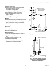
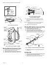
To install the controller:
1. Loosen the screw (at the top of the case, above the
scale setting), and remove the cover. Loosen the two
screws that secure the adapter clamp. (See Fig. 6).
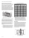
2. Insert the sensing element into the immersion well.
3. Fasten the case of the Aquastat Controller to the well
with the adapter clamp. Make certain that the clamp is
properly positioned over the groove of the well spud.
Also, be sure the flange at the opening of the well fits
snugly into the opening of the case. The sensing bulb
must bottom in the well.
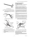
NOTE: Some models include up to 3 in. (76 mm) extra capil-
lary tubing inside the case. In these models, pull out
the extra tubing, if needed.