


L4006,7,8; L6006,7,8 AQUASTAT
®
CONTROLLERS
11 60-2104—10
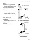
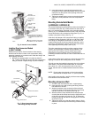
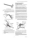
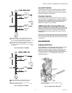
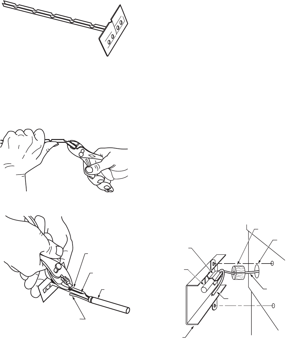
Fig. 12. Bulb support.
3. Break the holder to the desired length. (See Fig. 13).
NOTE: The holder must be long enough to hold the sensing
bulb in freely circulating air away from the duct wall.
Neatly coil the excess capillary at the controller case
or at the bulb holder.
Fig. 13. Removing excess bulb support.
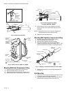
Fig. 14. Securing capillary in bulb holder.
4. Place the capillary in the bulb holder channel. Pinch the
top edges of the holder together at each segment. (See
Fig. 14).
5. Insert the bulb holder into the controlled area through the
hole prepared in step 1.
6. Fasten the bulb holder to the duct wall with the screws
provided.
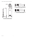
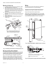
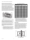
Mounting Remote Bulb Models
For Outdoor Air Sensing
These models have a 5 ft (1.5 m) capillary that establishes the
maximum distance between the case and the outdoor
mounting.
Install the bulb on the outside of the building in the shield
provided (See Fig. 15) where it can be exposed to
representative air temperature, but not to direct sunlight. Mount
the bulb high enough so that accumulated snow, leaves, or
other debris cannot obstruct circulation of air around it, and
where children cannot reach it. Avoid vents from the building.
Install the case at the indoor location selected, fastening the
screws through holes in the back of the case. Bring out the
bulb and tubing through a 3/4 in. (19 mm) hole in the outside
wall, avoiding sharp bends or kinks. Leave excess tubing
coiled near the case. Do not make sharp bends near the case
or bulb.
Slip the bulb through the supports in the shield. Pinch the split
supporting clip until it holds the bulb firmly in position. If the
seal-off tube protrudes from under the shield, bend it under as
shown in Fig. 15.
Hold the shield over the mounting position and form a small-
radius bend in the tubing. Place the split plug around the tubing
and move the shield into the mounting location as a unit. Push
the split plug into the hole until it is wedged securely in place.
Fasten the shield in place on the wall with the screws provided.
NOTE: If the tubing is properly shaped and the split plug
installed as directed, the shield will cover the split
plug, and the hole in the wall will be hidden from sight.
Fig. 15. Mounting bulb in shield outside building.
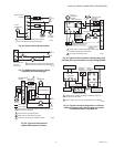
Mounting L6008A Remote Bulb Controller
Mounting with Guard Bracket
Mount the bulb in the guard bracket as shown in Fig. 16.
Locate the bulb and bracket combination, in freely circulating
air, in the controlled area. With screws provided, fasten the
bracket in place.
M8970A
M7216A
PINCH TOP EDGES OF
HOLDER TOGETHER
AT EACH SEGMENT
CAPILLARY
TUBING
SENSING
BULB
BE SURE EXTENSION TUBE IS
UNDER BULB HOLDER, AS SHOWN
M7217A
M8800A
INSERT BULB
IN CLAMP
OUTDOOR
SENSING
BULB
SEAL-OFF
TUBE
34886A
BULB
SHIELD
CAPILLARY
TUBING
SPLIT WOOD PLUG
3/4 IN.
(19 MM)
HOLE IN
WALL